
How to Create Your First Drawing in AutoCAD: A Practical Guide for Beginners
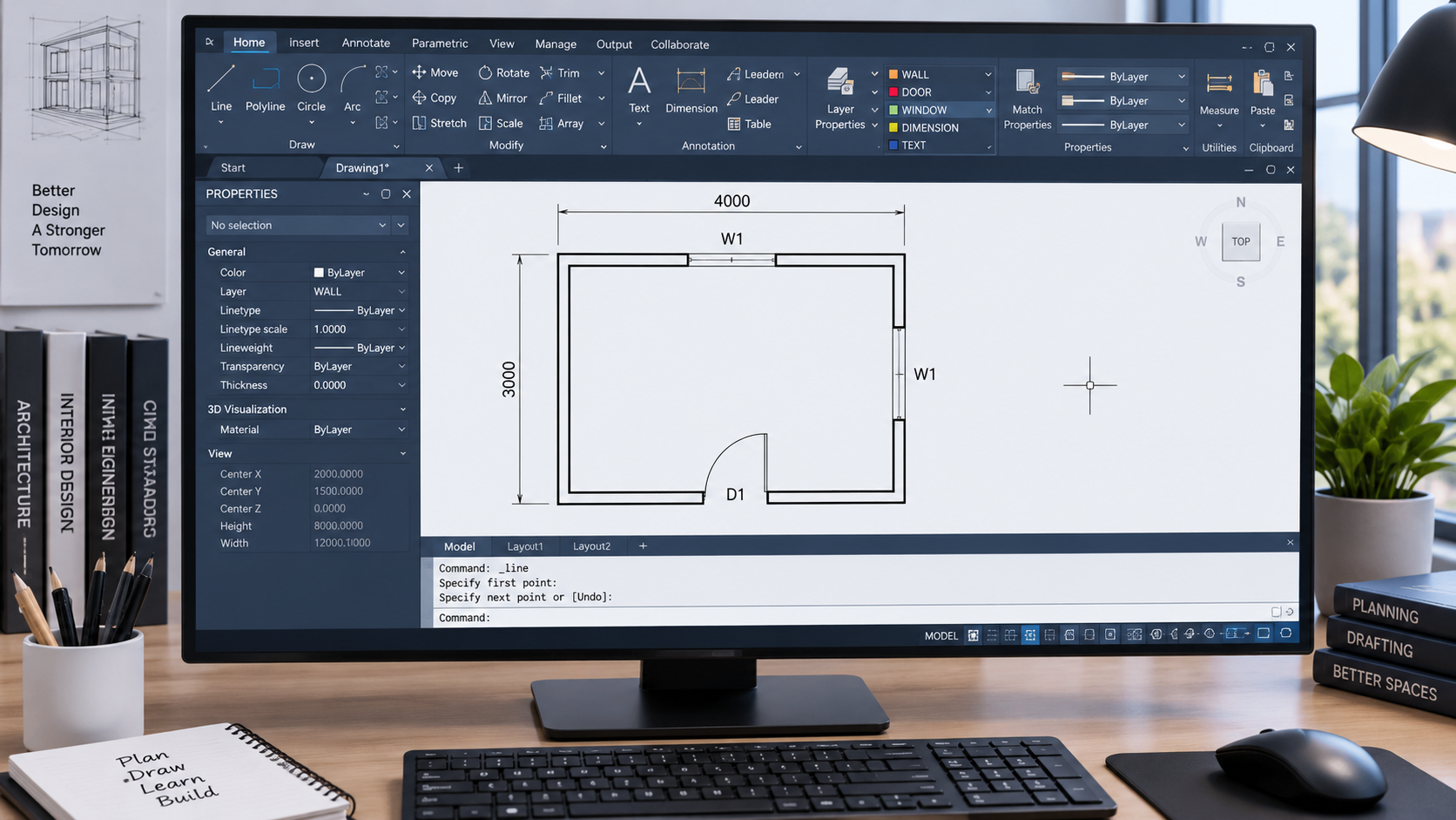
Hello engineers, architects, and AutoCAD designers! If you are opening AutoCAD for the first time, the interface might seem a bit daunting. Upon launching the software, you will see panels, toolbars, a command line, coordinates, layers, and various icons that you may never have used before. The good news is that you don’t need to learn everything before creating your first drawing.
We will share some basic tips to help you work effectively in AutoCAD, allowing you to kickstart your design career with a simple, practical drawing while learning essential tools along the way.
Beginners can also explore the official Autodesk AutoCAD beginner tutorials to understand the interface and basic drawing workflow.
In this guide, you will learn how to create a basic 2D architectural drawing in AutoCAD using commands such as LINE, OFFSET, TRIM, RECTANGLE, CIRCLE, MOVE, COPY, and DIM. We have intentionally kept this example simple so that beginners can follow along step-by-step.
Once you understand the basic AutoCAD workflow, you can use these skills to create detailed architectural floor plan drawings.
What You Will Learn
By completing this tutorial, you will learn how to:
- Create a new AutoCAD drawing
- Set drawing units
- Understand Model Space
- Use the command line
- Draw precise lines
- Create walls using the OFFSET command
- Remove excess geometry using TRIM
- Create doors and windows
- Draw a simple circle
- Move and copy objects
- Add dimensions
- Save your drawing correctly
- Organize a basic drawing using layers
You do not need advanced knowledge of AutoCAD to complete this tutorial.
What Drawing Will We Create?
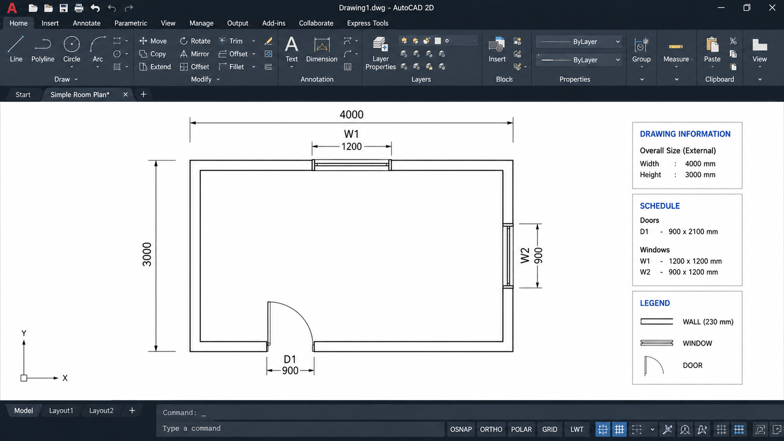
To start with our first project, let’s create a simple floor plan for a small room.
For example, suppose you need to draw a plan for a room of this size:
4 m × 3 m
We will include the following elements:
- Four walls
- One door
- Two windows
- Basic dimensions (measurements)
- Simple room labeling
This is the kind of basic exercise a beginner would undertake when learning architectural drafting.
Practical tip: Don’t worry about making the first drawing look beautiful. Your primary goal should be getting the measurements right and understanding how the commands work.
Step 1: Open AutoCAD and start a new drawing
First, open AutoCAD and create a new drawing.
Depending on your AutoCAD version, you might see options like:
- New Drawing → Start Drawing
If a standard 2D drafting template is available, select it.
For architectural work, it is beneficial to use real-world measurements rather than drawing everything at an arbitrary scale.
For a detailed introduction to the AutoCAD interface and starting a new drawing, see the official Autodesk tutorial.
AutoCAD is also useful for preparing an existing floor plan before renovation or remodeling work.
Step 2: Set Drawing Units
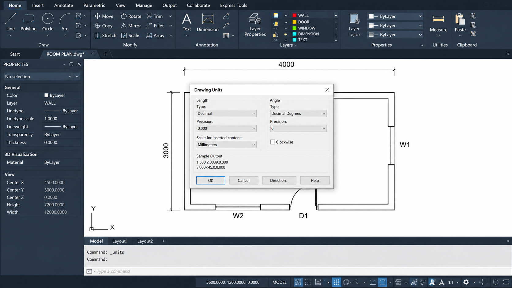
Before you draw anything, decide which units you are going to use.
Type:
- UNITS
and press Enter.
The Drawing Units dialog box will appear.
For a simple architectural exercise, you can use the following settings:
- Type: Decimal
- Precision: 0.00
- Insertion scale: The unit appropriate for your project
For this tutorial, we will assume that 1 drawing unit = 1 millimeter.
Therefore:
4000 units = 4000 mm = 4 meters
And:
3000 units = 3000 mm = 3 meters
This approach is useful because it allows you to work with actual construction dimensions.
Step 3: Understand Model Space
First, you need to understand that AutoCAD provides a large workspace known as ‘Model Space’.
This is where you create your actual drawing.
At this stage, do not worry about paper size or printing. Focus on creating the correct geometry first.
You can use the mouse wheel for the following actions:
- Scroll up → Zoom in
- Scroll down → Zoom out
- Press and hold the mouse wheel → Pan
Here is a useful shortcut:
- Z → Enter → E → Enter
This activates ‘Zoom Extents’ and fits your drawing within the available screen area.
Step 4: Create the outer room
Now, we will create a basic 4 m × 3 m room.
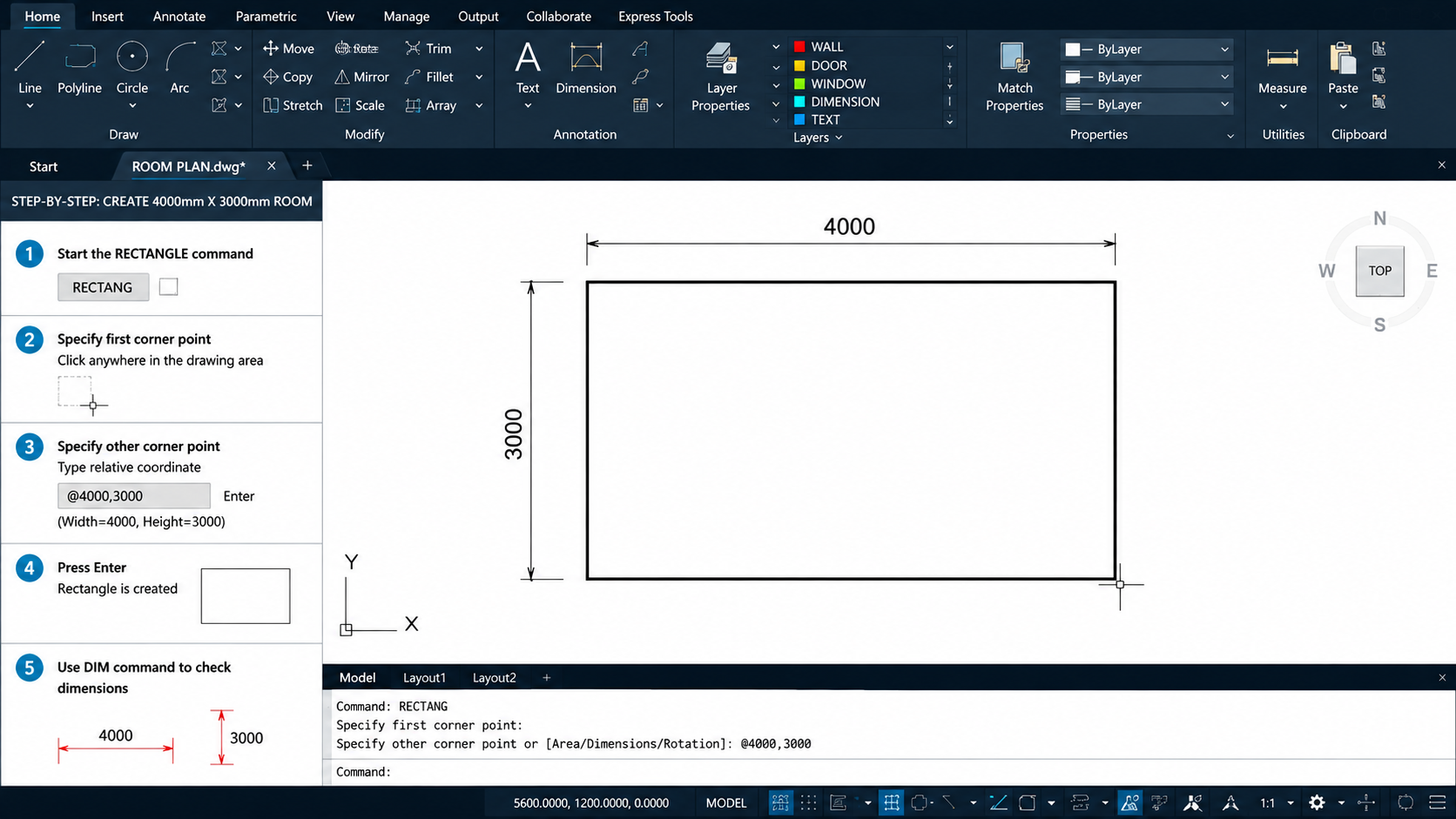
For beginners, the easiest way to do this is by using the RECTANGLE command.
Type:
- RECTANG
Press Enter.
Click on a starting point anywhere in the model space.
For example, click near the center-left area of your screen.
Now, enter the second corner using relative coordinates:
- @4000,3000
Press Enter.
AutoCAD will create a rectangle with the following dimensions:
4000 mm wide × 3000 mm high
This forms the basic outline of our room.
professional CAD drafting and manually sketching shapes by eye.
Why use coordinates?
Coordinates allow you to create precise geometry without relying on the exact position of the mouse.
This is one of the key differences between professional CAD drafting and manually sketching shapes by eye.
Step 5: Create wall thickness using OFFSET
You can see that you currently have just a rectangle representing the room’s boundary. In architectural drawings, we usually need to show wall thickness.
For this example, let’s assume the wall thickness is:
230 mm
Type:
OFFSET
Press Enter.
Enter:
230
Press Enter.
Select the rectangle.
Then, move your cursor towards the inside of the room and click.
AutoCAD will create a parallel rectangle representing the inner boundary of the wall.
You now have two boundaries:
- The outer wall line
- The inner wall line
This is one of the most useful AutoCAD techniques for architectural drawing.

Practical example
Instead of manually creating four separate wall lines and trying to maintain an exact thickness of 230 mm, OFFSET creates parallel geometry quickly and accurately.
After learning basic drawing commands, you can move on to detailed drawings such as a staircase design plan.
Step 6: Use TRIM to create openings
As you can see, the lines for the inner and outer walls are currently continuous.
We need openings for doors and windows.
This is where the TRIM command comes in handy.
Type:
TRIM
Press Enter.
Depending on your AutoCAD version, you can press Enter again to use all visible objects as cutting edges.
Select the parts of the wall you want to remove.
For example, create a door opening on the bottom wall.
You can remove a section approximately this wide:
900 mm
for a standard conceptual room door opening.
Important note: The dimensions used here are examples for learning AutoCAD. Actual dimensions for doors, windows, walls, and structural elements should be based on project requirements, building codes, and professional design standards.
Step 7: Create the Door
Now, let’s create a simple door.
Use the LINE command.
Type:
L
Press Enter.
Draw a line to represent the door leaf.
For example, you can create a door leaf that is 900 mm wide.
Then, use the ARC command to indicate the door’s swing direction.
Type:
ARC
Press Enter.
Draw a quarter-circle arc extending from the hinge point towards the opening area.
The final symbol should convey two things:
- Where the door is located
- The direction in which it opens
There is no need to make the symbol overly complex for an initial drawing.

Step 8: Add a window
Now, let’s add a simple window to one of the walls.
An easy method for beginners is to use the OFFSET command.
Let’s assume the window opening is 1200 mm wide.
Create the opening in the wall, and then add two parallel lines inside the opening to represent the window frame.
You can use these commands to create the basic geometry:
OFFSET
and:
TRIM
This introduces an essential AutoCAD workflow:
Draw → Offset → Trim → Clean
You will frequently use this pattern in architectural drafting.
Step 9: Add another window
Let’s repeat the same process for this second wall as well.
You can use the following command for this:
COPY
Instead of creating the second window from scratch…
Type:
COPY
Press Enter.
Select the window geometry.
Press Enter.
Specify a base point.
Then, specify a destination point.
This creates a duplicate copy of the selected geometry.
Why is COPY useful?
Imagine a large residential project that requires 30 identical windows.
Creating each window individually would be a waste of time.
Creating one perfect window and then copying it can significantly speed up the drafting process.
Step 10: Use MOVE to adjust the object's position
You need to understand that sometimes an object is created correctly, but its placement is wrong.
For example, your window might be too close to a corner.
You don’t need to delete and recreate it.
Use:
MOVE
Press Enter.
Select the object.
Press Enter.
Select a base point.
Move your cursor to the desired location and click.
It is a simple command, but it is very useful in large drawings.
Step 11: Add a simple circle
Let’s add a basic round object to the room.
For example, you can depict a small table or any other circular item.
Type:
CIRCLE
Press Enter.
Select the center point.
Enter the radius.
For example:
400
Press Enter.
You now have a circle with a radius of 400 mm.
This highlights another important point: AutoCAD allows you to create geometry using precise numerical values.
Step 12: Use Object Snap for precision
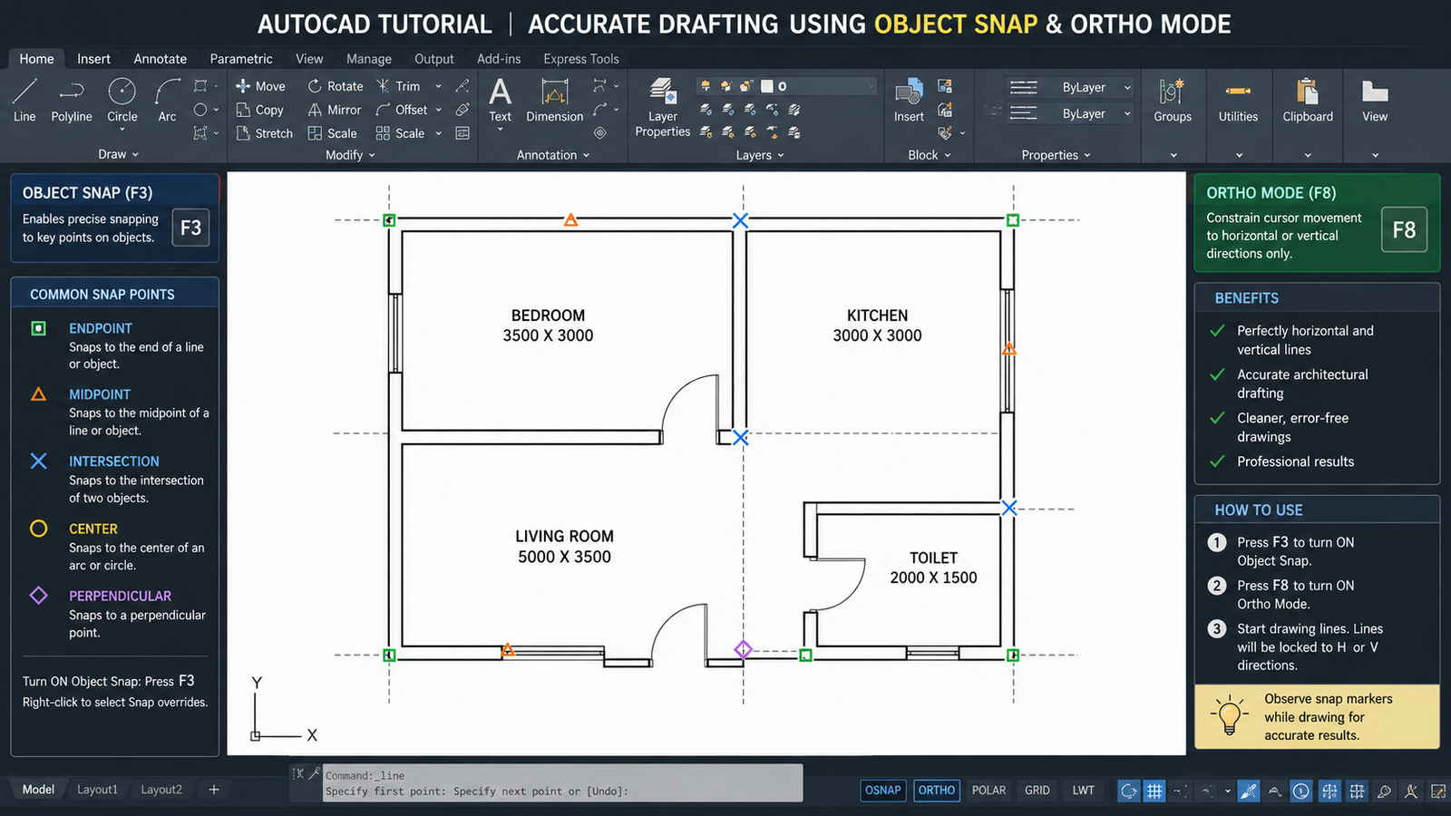
When drawing manually, it can be difficult to precisely select an object’s endpoint, midpoint, or center.
AutoCAD solves this problem using Object Snap (commonly referred to as OSNAP).
Press:
F3
To toggle Object Snap on or off.
Common Object Snap options include:
- Endpoint
- Midpoint
- Center
- Intersection
- Perpendicular
- Nearest
For introductory architectural drafting, Endpoint, Midpoint, Center, and Intersection are particularly useful.
Practical example
Suppose you want to connect a line precisely to the corner of a wall.
Instead of estimating the location with your mouse, use the Endpoint Snap.
AutoCAD will identify the exact endpoint.
That tiny difference can prevent various alignment issues later on.
Accurate drawings are important when preparing documents related to building plan approval rules.
Step 13: Turn on Ortho mode
Press:
F8
to turn on Ortho mode.
Ortho restricts your cursor movement to horizontal and vertical directions.
It is very useful when creating:
- Walls
- Floor plans
- Columns
- Structural grids
- Doors
- Windows
- Dimension lines
For example, if you are drawing a wall horizontally, Ortho helps prevent you from accidentally drawing a slightly slanted line.
Step 14: Add Dimensions
Adding dimensions is crucial; a drawing becomes much more useful when the necessary measurements are clearly displayed.
Use the DIM command.
Type:
DIM
Press Enter.
Select the first point.
Select the second point.
Then, place the dimension line in the correct position.
For our example, you can show the following dimensions:
- Total width = 4000 mm
- Total height = 3000 mm
- Door width = 900 mm
- Window width = 1200 mm
The dimension style and size should be adjusted according to your drawing standards.
Step 15: Add room labels
Adding room labels allows us to look at the floor plan and identify the purpose of each space.
Use the TEXT or MTEXT command.
For example, label the room like this:
BEDROOM
Or:
ROOM 01
You can use:
MTEXT
Use MTEXT for greater flexibility in text formatting.
Room labels should be clear and easy to read.
Do not use unnecessary decorative fonts in this technical drawing.
Step 16: Create Basic Layers
It is essential to create basic layers because as your drawings become more complex, keeping everything on a single layer can lead to confusion.
A better approach is to place different types of information on separate layers.
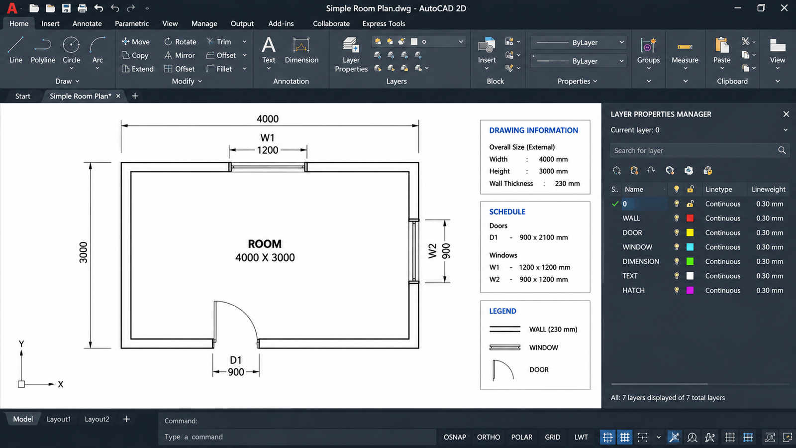
For example, you can create the following layers:
Layer Purpose
- WALL → Wall →geometry
- DOOR →Door→ symbols
- WINDOW → Window → geometry
- DIMENSION → Dimensions (measurements)
- TEXT → Room → labels
- FURNITURE → Furniture
- CENTER → Center lines
Open the ‘Layer Properties Manager’ and create the necessary layers.
Then, assign the objects to their respective layers.
Practical example
If you want to hide dimensions temporarily, you can simply turn off the ‘DIMENSION’ layer instead of selecting each dimension individually.
This is very useful for professional drawings.
Once you are comfortable with basic commands, practice creating a staircase plan and section with dimensions and details.
Step 16: Create Basic Layers
It is essential to create basic layers because as your drawings become more complex, keeping everything on a single layer can lead to confusion.
A better approach is to place different types of information on separate layers.
For example, you can create the following layers:
Layer Purpose
- WALL → Wall →geometry
- DOOR →Door→ symbols
- WINDOW → Window → geometry
- DIMENSION → Dimensions (measurements)
- TEXT → Room → labels
- FURNITURE → Furniture
- CENTER → Center lines
Open the ‘Layer Properties Manager’ and create the necessary layers.
Then, assign the objects to their respective layers.
Practical example
If you want to hide dimensions temporarily, you can simply turn off the ‘DIMENSION’ layer instead of selecting each dimension individually.
This is very useful for professional drawings.
Once you are comfortable with basic commands, practice creating a staircase plan and section with dimensions and details.
Step 17: Clean up the drawing
After creating the basic geometry, carefully review the drawing.
Pay attention to the following:
- Extra lines
- Unwanted overlaps
- Incorrect dimensions
- Misaligned objects
- Duplicate geometry
- Gaps in walls
- Incorrect door swings
- Objects placed on the wrong layer
Use these commands:
- TRIM
- EXTEND
- MOVE
- COPY
- ERASE
And:
FILLET
Use this only when necessary.
Creating a professional-looking CAD drawing is not just about generating geometry; cleaning up and organizing that geometry is equally important.
Step 18: Save your first AutoCAD drawing
Make sure to save your work regularly from now on.
Use this shortcut:
- CTRL + S
For your first exercise, use a meaningful filename, such as:
- First_AutoCAD_Room_Drawing.dwg
Avoid names like:
- drawing1.dwg
because it becomes difficult to identify them when you have a large number of files.
A good naming system can save time when working on multiple projects.
Useful AutoCAD Commands for Beginners
After completing your first drawing, it is beneficial to practice these commands.
- Command → Shortcut → Primary Use
- LINE → L → Creating straight lines
- RECTANGLE → REC → Creating rectangles
- CIRCLE → C →Creating circles
- OFFSET → O → Creating parallel geometry
- TRIM → TR → Removing unwanted parts
- EXTEND → EX → Extending objects
- MOVE → M → Moving objects from one place to another
- COPY → CO → Creating duplicate copies of objects
- ROTATE → RO → Rotating objects
- MIRROR → MI → Creating a mirror image
- ERASE → E → Deleting objects
- FILLET → F → Creating rounded corners
- DIM →DIM Adding → dimensions (measurements)
- MTEXT → MT → Adding text
- LAYER → LA → Managing layers
- UNITS → UN → Setting drawing units
You do not need to memorize all these commands on the very first day.
Start with a few selected commands and use them repeatedly.
You can practice essential commands such as lines, rectangles and other basic drawing tools through Autodesk’s official learning resources.
A Simple Beginner Practice Exercise
Once you have finished drawing the room, try creating another one without the help of the tutorial.
Create a room with these dimensions:
5000 mm × 3500 mm
Then, try adding the following elements:
- 230 mm walls
- A 900 mm door
- Two 1200 mm
- windows
- A round table
- Room label
- Overall dimensions
- Separate layers
Try to complete the drawing using only the commands you have learned.
This exercise will help you remember the commands better than simply reading about them.
Common Mistakes Beginners Make
1. Creating everything using the mouse
One of the most common mistakes is relying entirely on mouse movements.
For technical drawings where accuracy is crucial, always use numerical input.
2. Ignoring units
If your project requires millimeters but you start drawing without defining the units, you may face issues later on.
Set your units before creating the necessary geometry.
3. Not using Object Snap
Without OSNAP, objects might appear connected when, in reality, they could be slightly misaligned.
Use Endpoint, Midpoint, Center, and Intersection snaps whenever appropriate.
4. Placing everything on a single layer
A simple practice drawing might work with just one layer.
However, this won’t suffice for a professional project.
Start learning about layer organization right from the beginning.
5. Recreating the same object repeatedly
If you already have the correct geometry, use commands like COPY, MIRROR, or ARRAY to place it correctly instead of manually recreating it.
6. Forgetting to save
AutoCAD files can involve a significant amount of work.
Use Ctrl + S regularly and consider keeping backup copies of important drawings.
Time-saving keyboard shortcuts
Here are some shortcuts that are useful to remember:
- F3 — Object Snap
- F8 — Ortho Mode
- F10 — Polar Tracking
- F12 — Dynamic Input
- Ctrl + S — Save
- Ctrl + Z — Undo
- Ctrl + Y — Redo
- Esc — Cancel the current command
- Spacebar — Often acts like the Enter key to repeat a command
The more you use these shortcuts, the less you will need to search through menus.
What Should You Learn After Your First Drawing?
Once you can easily draw a simple room, move on to slightly more realistic architectural exercises.
A useful learning sequence is as follows:
First drawing → Basic floor plan → Doors and windows → Furniture layout → Dimensions → Layers → Blocks → Hatching → Layouts → Plotting
After this, you can start working on a complete residential floor plan.
You can also learn some more advanced topics, such as:
- Architectural drafting standards
- Structural drawing
- Electrical plans
- Plumbing layouts
- Section drawings
- Elevations
- Title blocks
- Paper Space
- Viewports
- Printing and plotting
Quick Beginner Checklist
Understand Model Space
Create a rectangle
Use OFFSET for wall thickness
Use TRIM for openings
Draw a door
Add windows
Practice COPY and MOVE
Use Object Snap
Use Ortho Mode
Add dimensions
Create basic layers
Add room text
Clean the drawing
Save the DWG file
Open a new AutoCAD drawing
Set the drawing units
Important Note
The dimensions in this tutorial are educational examples, not construction instructions. Actual architectural and construction drawings should be prepared according to the applicable local building regulations, project requirements, structural requirements, and professional standards.
Content note: This article is written from scratch in original wording and structure for educational use. It is not copied from a specific third-party article.
Conclusion
Creating your first AutoCAD drawing does not require knowing hundreds of commands. The most important thing is to understand the basic workflow and practice creating accurate geometry.
Start with a simple room. Draw the basic shape, create wall thickness with OFFSET, make openings with TRIM, add doors and windows, use Object Snap for accuracy, add dimensions, organize your objects into layers, and save the final DWG file.
Once these basic operations become familiar, AutoCAD becomes much less intimidating.
After mastering basic AutoCAD tools, you can gradually learn professional drawings such as RCC staircase section design.
The key is practice, accuracy, and repetition.
Your first drawing does not need to be perfect. It simply needs to teach you how the tools work.
Frequently Asked Questions
How do I create my first drawing in AutoCAD?
Start a new drawing, set the units, create basic geometry using commands such as LINE or RECTANGLE, and then practice OFFSET, TRIM, MOVE, COPY, and DIM.
Which AutoCAD commands should beginners learn first?
Beginners should start with LINE, RECTANGLE, CIRCLE, OFFSET, TRIM, MOVE, COPY, ERASE, DIM, and LAYER.
What units should I use for architectural drawings in AutoCAD?
Millimeters are commonly used for detailed architectural drawings. However, the correct unit should always match the requirements of your project
How can I draw accurately in AutoCAD?
Use numerical input, Object Snap (OSNAP), Ortho Mode, and appropriate coordinate methods instead of relying only on mouse movement.
What should I practice after creating my first AutoCAD drawing?
After a basic room drawing, practice complete floor plans, doors and windows, furniture layouts, dimensions, layers, blocks, hatching, layouts, and plotting.