
Architectural Floor Plan Drawings: Complete Guide to Planning, Design and Construction
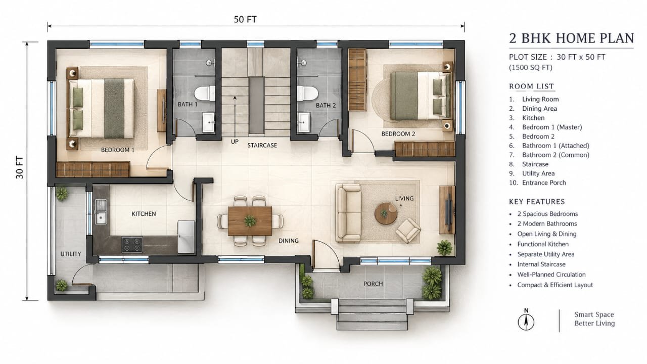
Architectural floor plan drawings are one of the most important parts of the building design process. Before a house, apartment, office, commercial building, or other structure is constructed, the proposed arrangement of rooms, walls, doors, windows, stairs, furniture, and circulation areas needs to be carefully planned.
A well-prepared architectural floor plan gives a clear picture of how a building will be organized. It helps architects and designers develop the layout, allows clients to understand the proposed spaces, and provides useful information for engineers, contractors, and other construction professionals.
For a homeowner, a floor plan can answer simple but important questions: Where will the bedrooms be located? Is the kitchen connected conveniently to the dining area? Will there be enough natural light and ventilation? How will people move from the entrance to the living spaces? Is there enough room for furniture?
For architecture and civil engineering students, learning how to understand and prepare floor plan drawings is an essential part of developing practical design skills.
In this guide, we will explore what an architectural floor plan is, why it is important, the major elements included in a floor plan, different types of floor plans, the basic process of creating one, common mistakes, useful software, and practical tips for preparing clear and functional architectural drawings.
What Is an Architectural Floor Plan?
An architectural floor plan is a scaled drawing that represents the arrangement of spaces within a building as viewed from above. It normally shows the relationship between rooms and other important building elements on a particular floor.
A typical architectural floor plan may include exterior and interior walls, doors, windows, stairs, columns, room names, dimensions, furniture, sanitary fixtures, kitchen elements, circulation spaces, and other architectural information.
Instead of looking at a building from the front or side, a floor plan allows you to understand the building horizontally. This makes it easier to study the size and relationship of different spaces.
For example, a residential floor plan may show an entrance leading into a living room, with a dining area and kitchen nearby. Bedrooms may be positioned in a more private zone, while toilets and utility spaces are arranged according to functional requirements.
A floor plan is therefore much more than a simple sketch. It is a method of communicating the planned organization of a building.
The amount of information shown depends on the purpose and stage of the drawing. A conceptual floor plan may contain only the basic arrangement of spaces, while a detailed construction drawing can contain dimensions, wall types, structural elements, fixtures, annotations, and other technical information.
Professional architectural floor plans follow recognized design principles for space planning, functionality, accessibility, and building performance. To understand these architectural design principles in more detail, you can read the Whole Building Design Guide (WBDG) published by the National Institute of Building Sciences.
Why Are Architectural Floor Plan Drawings Important?
Architectural floor plans are important because they allow a building design to be studied before physical construction begins.
A mistake in a drawing can often be corrected much more easily than a mistake discovered after construction has started. This is one reason why careful planning at the drawing stage is so valuable.
1. They Help Visualize the Building Layout
A floor plan provides a clear overview of the proposed building.
A client who may not understand technical architectural drawings can still use a well-presented floor plan to understand the basic arrangement of the house.
The drawing can show where the living room, bedrooms, kitchen, bathrooms, staircase, entrance, balcony, and other spaces are positioned.
2. They Improve Communication
Architects, civil engineers, structural engineers, contractors, interior designers, and clients need to communicate with each other during a building project.
A properly prepared drawing creates a common visual reference.
Instead of explaining every room and dimension verbally, professionals can refer to the same drawing.
This can reduce confusion and make design discussions more productive.
3. They Help Study Space Planning
Good architecture is not only about appearance. The spaces should also work properly for the people using them.
A floor plan makes it possible to study circulation, room relationships, furniture placement, entrances, openings, and usable floor area before construction.
For example, if a bedroom door opens directly into a furniture zone, the problem can be identified during planning and corrected before work begins.
4. They Support Cost Planning
A detailed floor plan provides useful information for estimating the approximate quantity of construction work.
Wall lengths, room sizes, openings, floor areas, and other measurable information can contribute to quantity calculations and preliminary cost estimation.
However, a floor plan alone should not be treated as a complete quantity or cost estimate. Detailed estimation normally requires additional drawings, specifications, structural information, and project data.
5. They Help With Construction Coordination
During construction, contractors and site teams need drawings to understand the intended arrangement of the building.
The architectural floor plan can be coordinated with structural, electrical, plumbing, and other drawings so that different parts of the project work together.
6. They Help Identify Problems Early
A floor plan allows designers to review a proposed layout before construction.
Potential issues such as narrow circulation areas, poorly positioned doors, insufficient furniture space, awkward room connections, or conflicts between openings can be identified at the design stage.
This makes the floor plan an important tool for design review.
Main Elements of an Architectural Floor Plan
A professional architectural floor plan normally contains several important elements. The exact information varies depending on the project and drawing purpose, but the following components are commonly found in detailed plans.
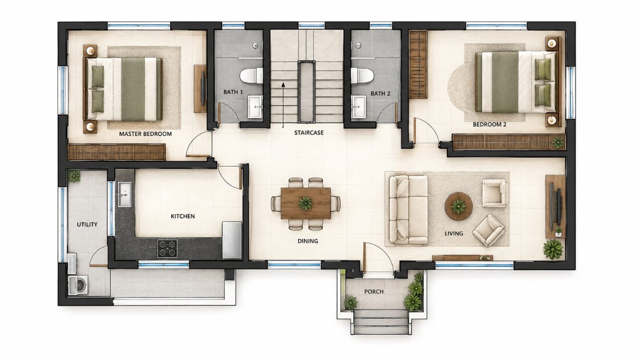
1. Exterior Walls
Exterior walls define the main boundary of the building.
They separate the internal spaces from the outside environment and are generally represented using clear and visually prominent linework.
The drawing should communicate the wall position and thickness accurately according to the design.
For example, a residential building may use different wall constructions depending on the structural system and local construction practice. Therefore, wall thickness should never be assumed to be identical for every project.
2. Interior Walls and Partitions
Interior walls divide the building into individual rooms and functional zones.
These may include bedroom walls, bathroom partitions, kitchen partitions, utility spaces, storage areas, and other internal divisions.
The layout of internal partitions has a direct effect on furniture placement, circulation, privacy, lighting, ventilation, and usable space.
3. Doors
Doors are an important part of floor plan design because they control movement between spaces.
A floor plan normally indicates the location and opening direction of a door. The door swing is particularly useful when checking whether furniture or another opening could interfere with its operation.
For example, a bedroom door should be positioned so that it does not create an unnecessary obstruction in the main circulation area.
Main entrance doors, bedroom doors, bathroom doors, service doors, and other openings may have different sizes and design requirements.
4. Windows
Windows are represented at their appropriate locations along walls.
Their placement affects natural light, ventilation, views, privacy, and the overall environmental quality of the building.
When planning windows, designers should consider the room function, orientation, neighboring buildings, privacy requirements, and local regulations.
A bedroom, living room, kitchen, and bathroom may require different approaches to window placement.
5. Room Names
Each major space should be clearly identified.
Typical room labels include:
- Living Room
- Dining Room
- Bedroom
- Master Bedroom
- Kitchen
- Toilet
- Bathroom
- Store
- Utility Room
- Study Room
- Pooja Room
- Lobby
- Balcony
- Parking
- Staircase
Clear room labels make the drawing easier to read and reduce confusion during design discussions.
6. Dimensions
Dimensions are one of the most important parts of a technical floor plan.
They communicate actual distances such as room length, room width, wall thickness, opening sizes, setbacks, and distances between important elements.
A well-organized dimensioning system should be easy to read without creating unnecessary visual clutter.
For example, a residential floor plan may include overall building dimensions as well as individual room dimensions.
Dimensions should be checked carefully before the drawing is issued.
Using proper layers makes architectural floor plans easier to read and edit. Learn the complete AutoCAD Layer Standards for Professional Submission Drawings to organize walls, doors, windows, text, dimensions, and furniture professionally.
7. Scale
Architectural drawings are normally prepared at a defined scale so that the relationship between the drawing and the actual building remains clear.
Common architectural scales include 1:50 and 1:100, although the appropriate scale depends on the size, purpose, and level of detail of the drawing.
A detailed room or construction detail may require a larger scale, while a complete building layout may use a smaller scale.
The scale should always be clearly indicated on the drawing.
8. North Arrow
A north arrow helps the reader understand the orientation of the building.
Orientation can be important when studying sunlight, ventilation, views, site access, and environmental conditions.
For residential projects, orientation may also be considered alongside local planning requirements and the owner’s preferences.
9. Staircase
In multi-level buildings, the staircase is a major component of the floor plan.
A staircase drawing should communicate the direction of movement, arrangement of steps, landing, width, and relationship with surrounding spaces.
The plan should be coordinated with the relevant section drawing because a floor plan alone cannot communicate all vertical dimensions.
10. Columns and Structural Elements
Depending on the drawing type, columns and other structural elements may also be shown.
Architectural and structural drawings should be coordinated so that the structural system does not create unexpected conflicts with doors, windows, furniture, circulation, or other architectural elements.
The exact representation of structural components should follow the requirements of the project and drawing set.
11. Furniture Layout
Furniture is sometimes included in architectural floor plans to demonstrate how the spaces can function.
A living room may show sofas, chairs, a television unit, and a coffee table. A bedroom may show a bed, wardrobe, and side tables.
Furniture layouts are useful because an empty room can appear larger than its actual usable space.
By adding furniture at an appropriate scale, designers can test whether the room provides enough space for everyday activities.
12. Kitchen Fixtures and Bathroom Fixtures
Kitchen and bathroom layouts often include fixed fixtures and equipment.
A kitchen plan may show counters, sink, refrigerator, cooking area, and storage.
A bathroom plan may show a toilet, wash basin, shower area, bathtub where applicable, and required circulation space.
These elements help designers check functionality before construction.
Types of Architectural Floor Plan Drawings
Floor plans can be categorized in different ways depending on the building type and purpose of the drawing.
Residential Floor Plans
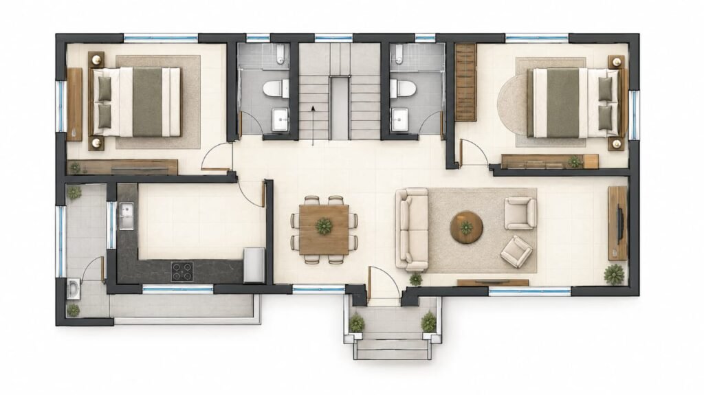
Residential floor plans are prepared for houses, villas, apartments, duplex homes, row houses, bungalows, and other living spaces.
The primary focus is usually comfortable living, functional circulation, privacy, natural light, ventilation, furniture arrangement, and efficient use of available space.
A residential floor plan may include spaces such as:
- Living room
- Dining area
- Kitchen
- Bedrooms
- Bathrooms
- Family room
- Study
- Store
- Utility area
- Balcony
- Staircase
- Parking
The exact combination depends on the size of the property and the requirements of the occupants.
Commercial Floor Plans
Commercial floor plans are used for offices, retail spaces, restaurants, clinics, showrooms, and other business-related buildings.
These layouts often require careful consideration of customer movement, staff circulation, service areas, storage, entrances, accessibility, emergency movement, and operational requirements.
For example, a restaurant floor plan needs to consider both customer seating and back-of-house functions such as kitchen, storage, washing, and service circulation.
Apartment Floor Plans
Apartment floor plans are designed around efficient use of limited space.
A successful apartment layout should create a practical relationship between living, sleeping, cooking, and service areas.
Open-plan living and dining areas are common in many contemporary layouts, while bedrooms and bathrooms are usually organized as more private zones.
Duplex House Floor Plans
A duplex house contains living spaces distributed across two levels.
The staircase becomes an important design element because it connects the two floors.
The designer must carefully coordinate the staircase with the entrance, living spaces, bedrooms, circulation, and structural system.
Villa Floor Plans
Villa floor plans generally provide more generous spaces and may include additional features such as large living areas, multiple bedrooms, dressing rooms, balconies, terraces, home offices, gardens, swimming pools, or entertainment spaces.
The challenge is to combine these features without making the circulation unnecessarily complicated.
Industrial Floor Plans
Industrial floor plans are prepared for factories, workshops, warehouses, production facilities, and related buildings.
These plans are strongly influenced by workflow, equipment placement, material movement, storage, worker circulation, safety requirements, and operational needs.
Unlike a residential plan, the primary focus may be production efficiency and logistics rather than domestic comfort.
Mixed-Use Floor Plans
Mixed-use buildings combine different functions within the same development.
For example, a building may contain shops on the ground floor and residential apartments on upper levels.
Such projects require careful separation of public and private circulation, services, entrances, parking, and building operations.
If you are looking for a real residential layout example, check our 30×50 House Plan article featuring a modern 1500 sq ft 2BHK floor plan with porch, lawn, kitchen, bedrooms, staircase, and proper space planning.
How to Create an Architectural Floor Plan
Creating a floor plan is not simply a matter of drawing rooms and adding dimensions. A good plan develops through several stages of research, planning, testing, and refinement.
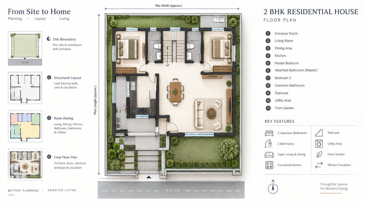
Step 1: Understand the Project Requirements
Start by understanding what the building needs to achieve.
For a house, collect information about:
- Plot dimensions
- Number of occupants
- Number of bedrooms
- Required bathrooms
- Kitchen requirements
- Parking needs
- Living and dining requirements
- Future expansion
- Storage needs
- Site access
- Orientation
- Budget considerations
- Local regulations
The requirements should be clear before the detailed layout is developed.
Step 2: Study the Site
The site has a major influence on the building layout.
Before preparing the floor plan, study the plot dimensions, road access, neighboring properties, site orientation, setbacks, existing structures, levels, and other relevant conditions.
For example, a plot facing a road on one side will have different planning considerations from a corner plot with road access on two sides.
Step 3: Establish the Building Envelope
The next stage is to understand the area available for construction after considering applicable setbacks and other planning requirements.
The building envelope establishes the basic boundary within which the floor plan can be developed.
Step 4: Divide Spaces According to Function
Start organizing the building into functional zones.
A simple residential project may be divided into:
- Public zone
- Semi-private zone
- Private zone
- Service zone
The living and entrance areas may form the public or semi-public portion of the home, bedrooms can be positioned in private areas, while the kitchen, utility, and service spaces can be grouped according to the project requirements.
This zoning approach can make the plan easier to understand and improve circulation.
Step 5: Position Major Spaces
Place the main rooms first.
For a house, this could mean deciding the approximate positions of the living room, bedrooms, kitchen, dining area, bathrooms, and staircase.
At this stage, avoid getting distracted by small details. First establish the overall relationship between spaces.
Step 6: Plan Circulation
Circulation refers to how people move through the building.
Check the route from the main entrance to the living room, bedrooms, kitchen, staircase, bathrooms, and other frequently used spaces.
Avoid unnecessarily long passages and awkward turns wherever possible.
Good circulation should feel natural rather than forced.
Step 7: Add Doors and Windows
Once the major spaces are established, place doors and windows.
Check door opening directions and make sure they do not create conflicts with furniture or other doors.
Windows should be positioned according to room function, natural light, ventilation, privacy, views, orientation, and applicable requirements.
Step 8: Add Furniture and Fixtures
Add furniture at a suitable scale to test the usability of each room.
This step can reveal problems that may not be obvious from walls alone.
For example, a bedroom may technically have enough floor area but still feel uncomfortable if the bed, wardrobe, and circulation space are not arranged properly.
Step 9: Add Dimensions
After the basic layout has been refined, add dimensions.
Start with major overall dimensions and then provide the necessary internal dimensions.
Make sure dimensions are consistent and do not contradict one another.
Step 10: Add Architectural Symbols and Notes
Add appropriate symbols, labels, levels, references, and notes required for the purpose of the drawing.
The drawing should communicate information clearly without becoming unnecessarily crowded.
Step 11: Check the Drawing
Before finalizing the floor plan, perform a complete review.
Check:
- Overall dimensions
- Room dimensions
- Wall thickness
- Door sizes and swings
- Window positions
- Staircase arrangement
- Furniture clearance
- Circulation
- Room labels
- North direction
- Scale
- Structural coordination
- Services coordination
- Drawing references
- General notes
A final review can catch many small errors before the drawing is issued.
Common Mistakes in Architectural Floor Plans
Even a visually attractive floor plan can have functional problems. Some common mistakes should be checked during the design process.
Poor Space Planning
Rooms may look acceptable individually but fail to work well together.
For example, placing a bathroom door directly facing an important living space may create privacy concerns.
Insufficient Circulation Space
Furniture and walls should not create uncomfortable movement paths.
Every room needs enough practical space for people to enter, move, use furniture, and perform everyday activities.
Incorrect Door Swing
A door can interfere with furniture, another door, or a narrow circulation area if its opening direction is not considered carefully.
Poor Window Placement
Windows should not be added simply to fill wall space.
Their location should be considered in relation to daylight, ventilation, privacy, orientation, and views.
Ignoring Furniture
A room may look spacious when shown without furniture but become difficult to use after furniture is installed.
Testing the layout with appropriately scaled furniture can prevent this problem.
Inconsistent Dimensions
One of the most serious drawing problems is inconsistent dimensioning.
The overall dimension should relate correctly to the internal dimensions. Any mismatch should be investigated before the drawing is issued.
Overcrowded Drawings
Adding too much information to a single drawing can make it difficult to read.
Use appropriate line weights, text sizes, dimensions, symbols, and annotations to maintain clarity.
Architectural Floor Plan Drawing Standards and Scale
Scale is an essential part of architectural drawing.
A drawing at 1:100 means that one unit on the drawing represents 100 units in reality.
For example, when working in millimeters, 10 mm on paper represents 1000 mm in the actual building at a 1:100 scale.
A 1:50 scale provides more detail than a 1:100 scale because the drawing is represented at a larger size.
The appropriate scale depends on the purpose of the drawing, paper size, building size, and level of information required.
It is also important to understand that scale alone does not guarantee accuracy. The dimensions and geometry of the drawing must still be checked carefully.
Using the correct drawing scale is essential for producing accurate construction documents. Beginners can learn more about architectural drawing scales and CAD standards through the official Autodesk Knowledge Network, which explains how scales, dimensions, and annotations are used in professional drafting workflows.
Architectural Floor Plan Drawings for Indian House Design
For residential projects in India, floor plan development often needs to consider the plot size, road location, local development regulations, setbacks, parking requirements, building height, ventilation, sanitation, and other applicable requirements.
For example, a 30 × 50 ft plot and a 40 × 60 ft plot cannot be planned in exactly the same way because the available building area and site proportions are different.
Similarly, a corner plot can provide different planning opportunities from an interior plot.
When preparing a house plan for approval or construction, the applicable local authority requirements should always be verified for the specific project location. Requirements can differ between cities and jurisdictions.
For a practical residential example, explore our complete 30×50 House Submission Drawing guide that explains site plans, floor plans, elevations, sections, setbacks, FAR calculations, and municipal approval requirements in India.
Architectural Floor Plan and Vastu Considerations
Some homeowners also want their house layout to consider Vastu principles.
Vastu-based preferences may influence the preferred locations of spaces such as the entrance, kitchen, bedrooms, staircase, and pooja room.
However, these preferences should be considered alongside practical architectural requirements such as site orientation, daylight, ventilation, structural planning, accessibility, circulation, and local regulations.
A good residential floor plan should ultimately be functional and suitable for the actual needs of the occupants.
Architectural Floor Plan vs Structural Plan
An architectural floor plan and structural plan are related but serve different purposes.
The architectural plan primarily communicates the arrangement and use of spaces. It focuses on walls, doors, windows, rooms, circulation, finishes, fixtures, and other architectural information.
The structural plan focuses on the structural system of the building. Depending on the project, it may include foundations, columns, beams, slabs, structural grids, reinforcement information, and other engineering details.
These drawings must be coordinated.
For example, a column should not unexpectedly appear in the middle of a doorway or interfere with an important architectural space because the architectural and structural layouts were developed without proper coordination.
Architectural Floor Plan vs Section and Elevation
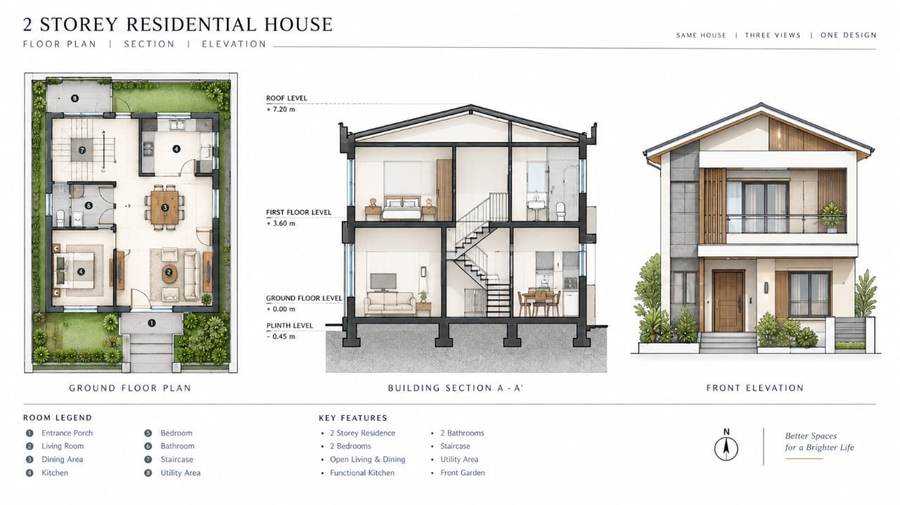
A floor plan, section, and elevation provide different views of the same building.
A floor plan shows the building horizontally from above.
An elevation shows the external appearance of a building from a particular direction.
A section represents a vertical cut through the building and helps explain floor levels, heights, slabs, stairs, roof construction, and other vertical relationships.
These drawings work together rather than replacing one another.
A complete architectural drawing set normally requires multiple views because no single drawing can communicate every aspect of a building.
A floor plan shows the horizontal layout of a building, while a section drawing explains vertical construction details such as foundation, plinth, slab, roof, staircase, and floor levels. Read our detailed Section Drawing for Building Submission guide to understand this drawing type.
Software Used for Architectural Floor Plan Drawings
Modern architectural floor plans are commonly prepared using CAD, BIM, and 3D modeling software.
AutoCAD
AutoCAD is widely used for 2D architectural drafting.
It is useful for preparing precise floor plans, dimensions, annotations, details, and construction drawings.
For students and beginners, learning commands such as Line, Polyline, Offset, Trim, Extend, Move, Copy, Rotate, and Dimension can provide a strong foundation for 2D drafting.
If you’re new to architectural drafting, start with our AutoCAD Basics for Beginners guide and then learn the 10 Essential AutoCAD Commands for Beginners before creating your first floor plan.
Revit
Revit uses a BIM-based workflow and allows architectural elements to be modeled as building components.
A change to the model can be reflected across related views, making it useful for larger projects and coordinated documentation.
SketchUp
SketchUp is often used for conceptual 3D design and quick visualization.
Designers can use it to understand spatial relationships and communicate design ideas before developing detailed documentation.
Other Floor Plan Tools
Depending on the project, professionals may also use dedicated floor planning, BIM, rendering, and visualization software.
The important point is that software is only a tool. Good floor planning still depends on understanding space, dimensions, construction, circulation, and the needs of the occupants.
Building Information Modeling (BIM) has become an important workflow for modern architectural projects because it helps coordinate architectural, structural, and MEP drawings in a single digital model. The official Autodesk Revit Learning resources provide a good introduction to BIM-based architectural design and documentation.
Tips for Creating Better Architectural Floor Plans
If you are learning architectural drafting or preparing house plans professionally, the following habits can improve your drawings.
Keep the Layout Functional
Do not focus only on making the plan visually attractive. Every room should have a clear purpose and practical relationship with adjacent spaces.
Think About Movement
Imagine yourself walking through the building.
Start at the entrance and move through the house step by step.
This simple exercise can reveal circulation problems.
Consider Natural Light and Ventilation
Try to provide appropriate openings based on the orientation, climate, room function, privacy, and applicable regulations.
Use Furniture as a Design Test
Place realistic furniture sizes in the plan.
This helps determine whether the room actually works rather than simply appearing large on paper.
Keep Services Practical
Kitchen, bathrooms, utility areas, and other service spaces should be planned with plumbing and service routes in mind.
Grouping wet areas where appropriate can simplify service coordination, but the final arrangement depends on the building design and site conditions.
Maintain Drawing Consistency
Use consistent text styles, dimensions, symbols, line weights, and annotation methods throughout the drawing.
A clean drawing is easier to understand and easier to coordinate.
Review the Plan at Different Levels
Look at the plan as a homeowner, architect, engineer, and contractor.
Each perspective can reveal different issues.
Architectural Floor Plan Checklist
Before considering a floor plan complete, check the following:
- Is the plot size correct?
- Are the overall building dimensions correct?
- Are room dimensions clearly shown?
- Are wall thicknesses consistent with the intended construction?
- Are doors positioned correctly?
- Are door swings practical?
- Are windows placed appropriately?
- Is natural light considered?
- Is ventilation considered?
- Is furniture placement practical?
- Is circulation comfortable?
- Is the staircase properly planned?
- Are room names correct?
- Is the north direction indicated?
- Is the drawing scale mentioned?
- Are structural elements coordinated?
- Are service areas practical?
- Are dimensions consistent?
- Are unnecessary lines and annotations removed?
- Has the drawing been reviewed against applicable local requirements?
This checklist is useful for both students and professionals because small drafting errors can create confusion later in the project.
Final Thoughts
Architectural floor plan drawings are the foundation of effective space planning. They transform an idea into a clear visual representation that can be discussed, reviewed, modified, and eventually developed into a complete building design.
A successful floor plan is not simply a collection of rooms inside a boundary. It is a carefully organized relationship between spaces, circulation, openings, furniture, structure, services, natural light, ventilation, and the needs of the people who will use the building.
Whether you are an architecture student learning basic drafting, a civil engineering student developing drawing skills, an architect preparing a residential layout, or a homeowner trying to understand a proposed house design, learning how to read and prepare floor plans is extremely valuable.
The best floor plans combine accuracy, functionality, clarity, and practical design thinking. Before moving from a concept to construction, every important dimension, opening, circulation route, structural requirement, and applicable regulation should be reviewed carefully.
A well-prepared architectural floor plan can make the entire building design process easier to understand and coordinate—from the first planning idea to detailed construction documentation.
Frequently Asked Questions
What is an architectural floor plan?
An architectural floor plan is a scaled drawing that shows the arrangement of spaces and architectural elements on a building level as viewed from above. It can show walls, doors, windows, rooms, stairs, dimensions, furniture, fixtures, and other information depending on the purpose of the drawing.
Why is a floor plan important?
A floor plan helps communicate the building layout before construction. It allows designers and clients to review room sizes, circulation, openings, furniture placement, and spatial relationships.
What should be included in a house floor plan?
A house floor plan may include rooms, walls, doors, windows, dimensions, staircase, furniture, kitchen fixtures, bathroom fixtures, room labels, orientation, and other project-specific information.
What scale is commonly used for architectural floor plans?
Scales such as 1:50 and 1:100 are commonly used, but the appropriate scale depends on the drawing purpose, building size, paper size, and required level of detail.
Can I create a floor plan in AutoCAD?
Yes. AutoCAD is commonly used for creating accurate 2D architectural floor plans. It provides tools for drawing walls, openings, dimensions, annotations, layers, and other drafting elements.
Why are dimensions important in a floor plan?
Dimensions communicate actual sizes and distances. Without clear dimensions, contractors and other professionals may not have sufficient information to accurately interpret the intended layout.
Should furniture be shown on an architectural floor plan?
Furniture can be included when it helps demonstrate space planning and functionality. However, the amount of furniture information depends on the purpose and stage of the drawing.
Is a floor plan enough to construct a building?
Usually, no. A construction project normally requires a coordinated set of drawings and documents, which may include architectural plans, elevations, sections, structural drawings, electrical drawings, plumbing drawings, schedules, specifications, and other project-specific documents.