
How to Prepare a Building Section Drawing for Submission: A Practical Guide
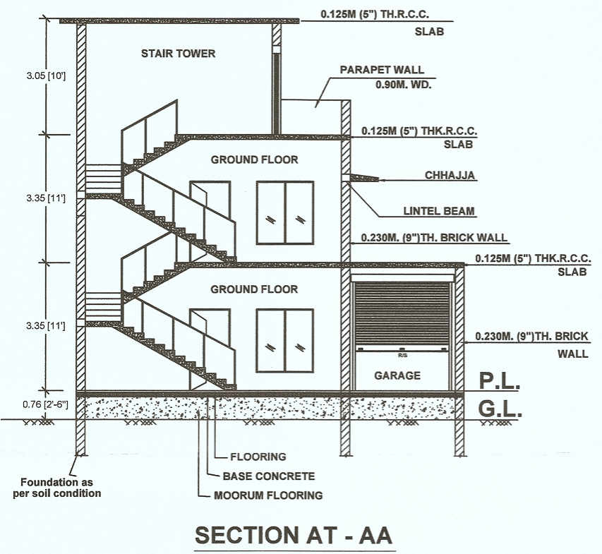
A building section drawing explains the vertical arrangement of a proposed building through an imaginary cut across the structure. It allows architects, civil engineers, draftsmen and building plan reviewers to understand the relationship between floors, stairs, roof levels and internal spaces.
Unlike a floor plan, which mainly communicates the horizontal layout, a section drawing reveals how the building works vertically. It can help clarify changes in floor height, double-height spaces, sloping sites, staircase connections and roof configurations.
Preparing a useful section drawing involves more than cutting through the building model and adding dimensions. The selected section must communicate the important design information clearly and agree with the corresponding architectural drawings.
This guide explains how to select a suitable section line, develop the drawing, coordinate vertical dimensions and review the final sheet before building submission.
1. Understand the Purpose of the Section Before Drafting
The first step is to determine what the section needs to explain. A section should answer specific questions about the building rather than simply reproduce its outline.
For example, a residential building section may need to explain how the ground floor connects to the upper floor, how the staircase reaches the next level, how the roof sits above the occupied spaces and how the building relates to the surrounding ground.
Before drafting, identify the important features that must appear in the section:
The relationship between the different floor levels.
The vertical arrangement of rooms and circulation spaces.
The staircase and its connection to each floor.
The roof, terrace or sloping roof profile.
Changes in ground level, where relevant.
Important openings, double-height spaces or other architectural features.
The vertical dimensions needed to understand the proposed design.
The exact information required depends on the building type and the submission rules of the concerned authority.
When preparing architectural drawings for building approval, consult the relevant provisions of the National Building Code of India along with the applicable local building regulations.
2. Select the Most Informative Section Line
A section line determines which parts of the building will be visible in the resulting drawing. A poorly positioned cutting line may leave important features unexplained, even when the drawing is technically neat.
Study the floor plan before choosing the section location. Identify areas where the vertical relationship between spaces needs clarification.
For a typical residential building, a useful section may pass through the staircase, floor slabs and important rooms. If the building contains a double-height living area, basement, split levels or a sloping roof, the section should be positioned to explain those features when they are relevant to the submission.
Consider these points while selecting the cutting line:
Choose a route that explains the main vertical arrangement.
Include the staircase when its configuration is important to understanding the building.
Avoid cutting through a feature that does not help explain the design.
Check whether another section is necessary to show a different part of the building.
Mark the section reference and viewing direction clearly on the relevant floor plan.
Label the drawing consistently, such as Section A–A or Section B–B. The reference shown on the floor plan must match the title of the corresponding section drawing.
3. Establish a Reliable Vertical Reference
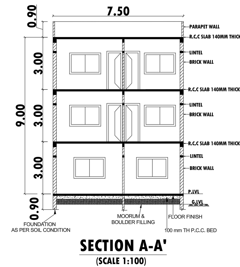
Vertical dimensions become difficult to interpret when different drawings use inconsistent reference levels.
Before adding dimensions, identify the reference datum used by the project. Depending on the site and the applicable drawing conventions, this may involve existing ground level, proposed ground level or another defined project reference.
Then establish the relevant floor and roof levels from the actual design.
Typical labels may include:
Existing Ground Level (EGL), where applicable.
Natural Ground Level (NGL), where applicable.
Proposed Ground Level.
Plinth Level.
Ground Floor Finished Floor Level.
First Floor Finished Floor Level.
Terrace or Roof Level.
Parapet Level.
These labels should be used only where they accurately describe the project conditions.
For a sloping site, do not assume that the ground level is identical on every side of the building. Show the relevant ground profile and levels according to the available site information and the submission requirements.
A consistent vertical reference helps the reviewer understand the building’s position relative to the site and reduces confusion when comparing drawings.
4. Develop the Section from the Actual Building Design
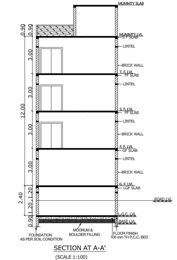
Once the cutting line and vertical references are established, develop the section using the coordinated architectural design.
In a CAD workflow, the section can be created from the building model, drafted using the relevant plans and elevations, or developed through a combination of these methods. Regardless of the workflow, the final representation must reflect the intended building geometry.
Include the elements that are actually intersected by the cutting plane and the visible elements needed to explain the space beyond it.
Pay attention to:
Floor slabs and their relationship to the finished floor levels.
Walls and openings intersected by the section.
Stair flights, landings and connecting floors.
Roof slabs, roof slopes or terrace arrangements.
Relevant beams, columns or other structural elements where required.
Ground profiles, plinths and below-ground spaces where applicable.
Use line weights and material hatching to distinguish cut elements from objects viewed beyond the cutting plane. The exact graphical conventions should follow the project’s drawing standards and any authority-specific requirements.
Do not add construction details that have not been established by the design. If a structural or foundation detail requires engineering confirmation, coordinate it with the responsible professional.
5. Dimension the Vertical Arrangement Clearly
Vertical dimensions should explain how the building is arranged, rather than create a crowded drawing.
Select dimensions that communicate the relationship between significant levels and spaces. Depending on the project, these may include floor-to-floor heights, clear room heights, plinth height, roof levels and overall building height.
Use dimension lines and level markers consistently. Keep the written values readable and position them so they do not obscure walls, stairs or important architectural features.
Floor-to-floor height and clear room height
These two measurements describe different things.
Floor-to-floor height is the vertical distance between the designated floor levels of two successive storeys. Clear room height refers to the usable vertical space within a room, measured between the appropriate finished surfaces.
The difference depends on the slab, ceiling arrangement and other elements within that vertical zone. Consequently, these values should not automatically be treated as identical.
Overall building height
Overall building height should be determined according to the measurement definition used by the relevant building regulations. The applicable starting level and the treatment of roof features or other elements may vary.
Use verified dimensions from the coordinated design and confirm the regulatory measurement method before finalizing the drawing.
6. Represent the Staircase Accurately
The staircase is often one of the most informative parts of a building section because it connects different levels and demonstrates vertical circulation.
When the cutting plane passes through the staircase, show the arrangement of flights and landings clearly. The drawing should communicate how the stair rises from one level to another and how it connects with the adjoining floor spaces.
Depending on the drawing requirements, verify:
The relationship between stair flights and floor levels.
The position and elevation of intermediate landings.
The intended riser and tread arrangement.
The available headroom.
The stair opening through the relevant floor slab.
The connection between the upper landing and the next floor.
Coordinate these features with the staircase layout in the floor plan. A section that looks visually plausible may still be misleading if the flight direction, landing position or floor opening does not match the plan.
Detailed structural design and code compliance should be confirmed separately wherever required.
7. Coordinate the Section with Plans and Elevations
A section is part of a coordinated drawing set, not an independent illustration. Its geometry and dimensions must agree with the other architectural views.
Start by comparing the section with the floor plans. Confirm that the walls, staircase, room arrangement and major openings correspond to the intended cutting location.
Next, compare the section with the elevations. Check that the floor levels, roof profile, parapet and external openings represent the same building design.
Use this focused coordination review:
Floor plans: Confirm the section location, room arrangement, wall positions and staircase configuration.
Elevations: Compare the external openings, floor levels, roof profile and visible projections.
Other sections: Check shared levels and repeated building elements.
Area and height information: Confirm that any reported values are based on the coordinated design and applicable measurement rules.
When a design revision changes the position of a wall, floor, stair or roof, review every affected view. Updating only one drawing can leave contradictory information in the final submission set.
For a better understanding of how different architectural drawings work together, explore our G+1 house submission drawing set before finalizing your building section.
8. Prepare the Section Sheet for Easy Reading
A technically correct drawing can be difficult to review if its information is poorly arranged.
Organize the sheet so the section is the main focus. Use a clear drawing title, appropriate scale, readable dimensions and consistent level symbols.
Before exporting the drawing, check the following presentation details:
The section title matches the reference on the floor plan.
The drawing scale and units are stated correctly.
Level markers can be distinguished from ordinary dimensions.
Text remains readable at the intended print size.
Hatching does not hide important outlines.
Dimension lines do not overlap room labels or architectural features.
The title block and revision information are current.
The exported PDF shows the complete drawing without clipped notes or dimensions.
The appropriate scale depends on the building size, sheet format, required level of detail and the authority’s submission standards. Use the scale specified by the project or the concerned authority rather than assuming that one scale is suitable for every case.
9. Common Section Drawing Problems and Their Solutions
Incorrect floor levels
Problem: Floor levels differ between the section and the floor plans.
Solution: Return to the coordinated design information, verify the intended levels and update all affected view
Staircase does not align with the plan
Problem: The drawing does not distinguish the relevant ground condition from the proposed building levels.
Solution: Use the verified site information and clearly identify the applicable ground references.
Inconsistent roof information
Problem: The section and elevation show different roof or parapet arrangements.
Solution: Confirm the intended roof design and coordinate the affected architectural views.
Overcrowded dimensions
Problem: Important values are difficult to read because several dimensions and notes overlap.
Solution: Reorganize the dimension strings, remove redundant annotations and use a consistent text style.
Unverified construction details
Problem: Foundation, slab or structural information has been copied from another project without confirmation.
Solution: Use project-specific information approved by the responsible designer or engineer and include only the details appropriate to the submission.
10. Final Review Before Exporting the Drawing
A final review should concentrate on whether the section communicates the design correctly and whether the submitted sheet matches the rest of the drawing package.
Use the following review points:
The section line and viewing direction are correctly identified.
The vertical reference levels are clear and consistent.
Floor-to-floor heights and other dimensions match the coordinated design.
The staircase and roof arrangement are represented accurately.
Ground conditions are shown where relevant.
The section agrees with the floor plans and elevations.
Drawing labels, scale, units and revision details are correct.
The exported PDF is legible and complete.
Any additional information required by the concerned authority has been included.
This review is intended to identify drafting and coordination problems. It does not replace a professional design review or a check against the applicable local building regulations.
Before submitting your final drawing package, use our building submission drawing checklist to review the required documents and verify that the architectural drawings are ready for submission.
Before finalizing the submission, review the applicable development and building regulations and confirm the drawing requirements specified by the concerned local authority.
Conclusion
A well-prepared building section drawing explains the vertical organization of a building in a clear and technically coordinated way. Its value comes from the correct selection of the section line, reliable level information, accurate staircase and roof representation, and consistency with the other architectural views.
By following a structured drafting and review process, architects and CAD professionals can make their section drawings easier to understand and reduce avoidable discrepancies within a building submission package.
The final drawing should always reflect the actual project design and follow the submission requirements of the relevant local authority.
Frequently Asked Questions
What is the main purpose of a building section drawing?
Its main purpose is to explain the building’s vertical arrangement, including floor relationships, staircases, roof configuration and relevant height information that cannot be fully understood from a floor plan alone.
How do I choose a section line for a building?
Choose a cutting line that reveals the most important vertical relationships in the proposed design. Consider the staircase, floor connections, roof arrangement, double-height spaces and any other features that require clarification.
What is the difference between a building section and an elevation?
A section represents a vertical cut through the building and explains internal vertical relationships. An elevation shows the external face of the building as viewed from a particular direction.
Should every building submission contain two sections?
Not necessarily. The required number and location of sections depend on the building’s complexity and the rules of the concerned authority. Some projects may need multiple sections to communicate different parts of the design.
Is one drawing scale suitable for every section?
No. The appropriate scale depends on the size of the building, sheet format, required level of detail and the authority’s submission standards.
Why should section drawings be checked against floor plans?
The comparison confirms that walls, staircases, openings, floor levels and other building elements are represented consistently across the drawing set.