
G+1 House Submission Drawing Set: Complete Guide for Building Plan Approval in India
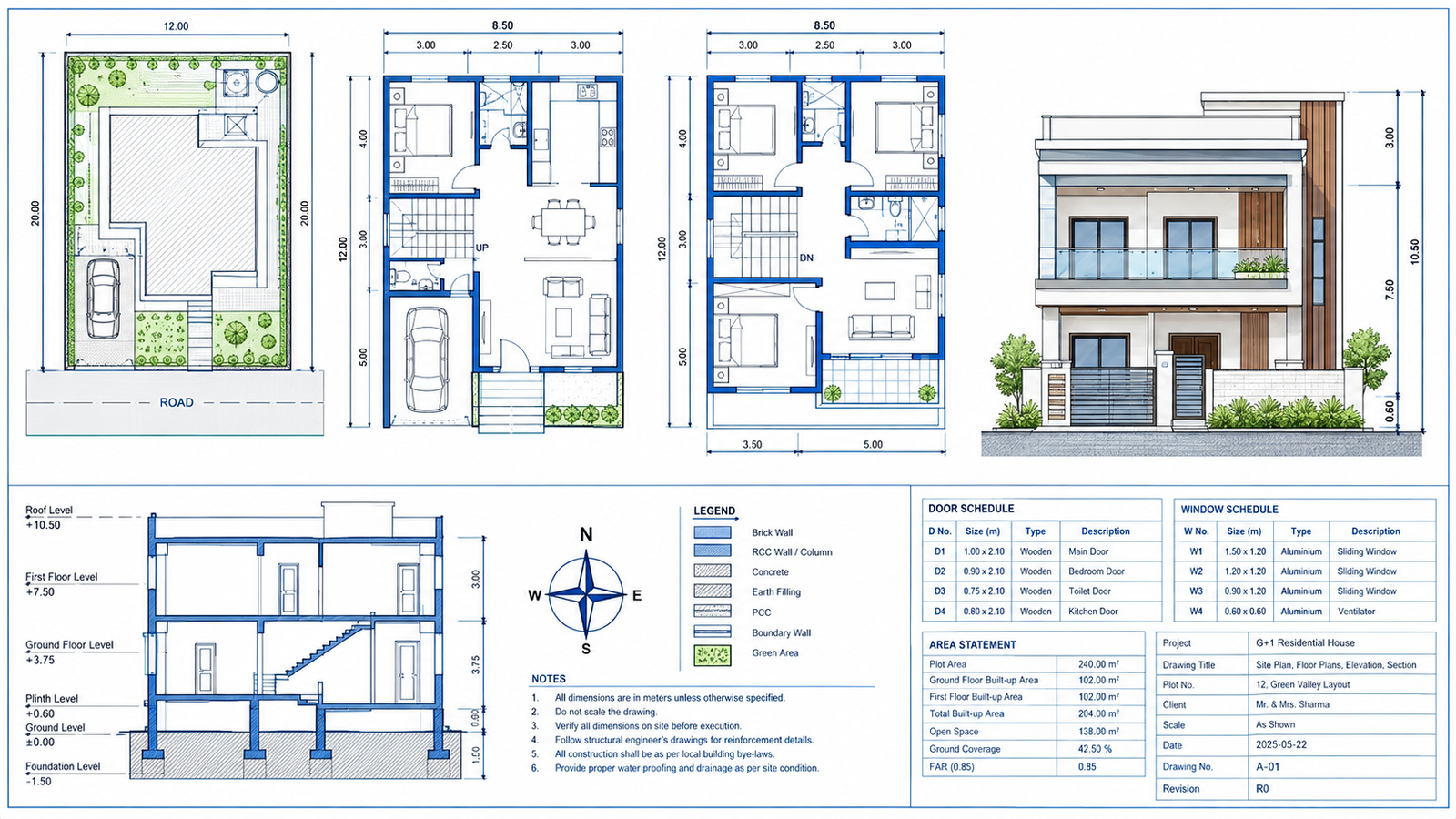
Planning a new G+1 house is exciting, but before construction begins, one important step cannot be skipped—building plan approval. Every residential project requires a complete submission drawing set that is presented to the local municipal authority or development authority for approval. These drawings explain every important detail of the proposed building, including its location, dimensions, height, layout, and structural information.
Whether you are an architect, civil engineer, architecture student, or homeowner, understanding the complete G+1 submission drawing set helps you prepare accurate drawings and avoid approval delays.
This guide explains each drawing included in a G+1 house submission set, why it is required, what information it contains, common mistakes to avoid, and professional drafting tips for AutoCAD users.
When preparing a G+1 house plan, it is important to consider applicable building regulations and safety requirements. The National Building Code of India 2016 provides a broad framework covering building requirements, fire safety, structural design, construction practices, and building services.
What is a G+1 House Submission Drawing Set?
A G+1 House Submission Drawing Set is a collection of technical architectural drawings prepared for obtaining permission to construct a Ground Floor plus First Floor residential building. Instead of submitting a single floor plan, authorities require multiple drawings that together describe the complete building proposal.
The drawing set demonstrates that the building follows local building bye-laws, zoning regulations, setback rules, height limits, parking requirements, and safety standards. Once approved, these drawings become the official reference during construction.
In simple words, submission drawings create a bridge between the building design and legal construction approval.
Why Submission Drawings Are Important Before Construction
Many homeowners think construction can begin immediately after preparing a house plan. In reality, construction without approved drawings may lead to penalties, notices, or demolition in some jurisdictions.
A professionally prepared submission drawing set helps:
Obtain building permission from municipal authorities.
Verify compliance with local building bye-laws.
Show proper setbacks and open spaces.
Calculate built-up area, plot coverage, and FAR/FSI.
Ensure proper drainage, ventilation, and structural planning.
Reduce construction errors during execution.
Approved drawings also become useful during utility connections, property documentation, and future renovations.
What Is Included in a Complete G+1 Submission Drawing Set?
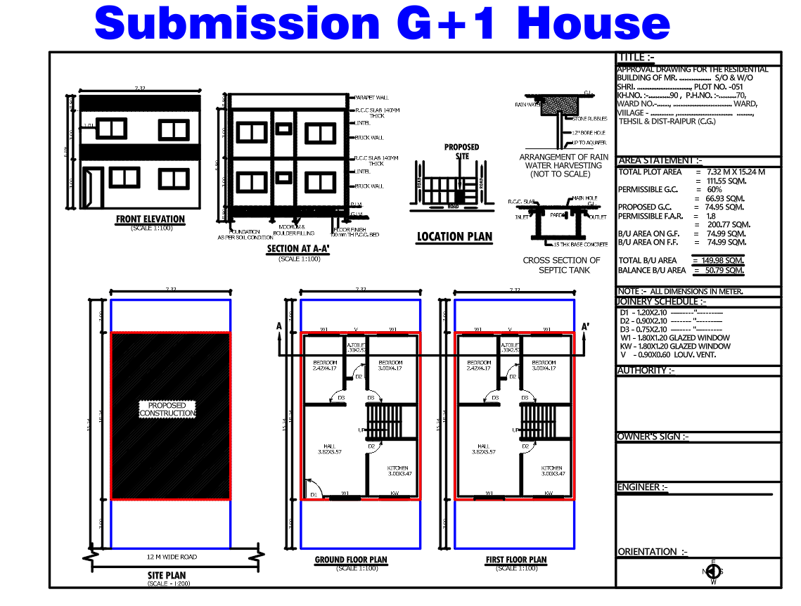
A standard residential submission drawing set generally includes:
Site Plan
Ground Floor Plan
First Floor Plan
Terrace or Roof Plan
Front Elevation
Side Elevation (where required)
Building Section
Foundation Plan
Structural Layout
Area Statement
Door and Window Schedule
Construction Notes
Title Block and Project Information
Each drawing serves a different purpose during the approval process.
Site Plan – The First Drawing in Every Submission Set
The site plan is one of the most important drawings because it shows how the proposed building sits within the plot boundaries.
It provides a top view of the entire property and nearby surroundings so authorities can verify whether the building respects required open spaces and access roads.
Information Included in a Site Plan
A professional site plan contains:
Plot dimensions.
Plot number.
North direction.
Road width and road location.
Entry gate.
Building footprint.
Front, rear, and side setbacks.
Compound wall.
Parking location.
Septic tank or sewer connection.
Rainwater harvesting location (if applicable).
Water tank location.
Existing structures (if any).
The site plan is usually prepared at a smaller scale because it covers the complete plot along with nearby roads and neighboring properties.
A complete G+1 project may require a site plan, floor plans, elevation, section and other technical drawings. For a detailed explanation, see our G+1 House Submission Drawing guide.
Why the Site Plan Is Important
The site plan helps authorities verify:
Building position within the plot.
Required setbacks.
Road alignment.
Accessibility.
Ground coverage percentage.
Plot utilization.
Without a clear site plan, building approval is usually incomplete.
Ground Floor Plan – Functional Layout of the Ground Level
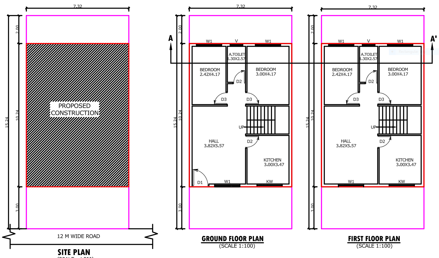
The ground floor plan explains the arrangement of all rooms located on the ground floor.
It is one of the most detailed drawings because it includes dimensions, wall thickness, openings, staircase position, furniture layout, and circulation space.
For a preliminary understanding of construction costs, readers can also refer to the latest CPWD Plinth Area Rates, while keeping in mind that actual construction costs vary by location, specifications, materials, labour and design.
Typical Rooms in a G+1 Ground Floor
A residential G+1 house may include:
Living Room.
Drawing Room.
Dining Area.
Kitchen.
Bedroom.
Attached Bathroom.
Common Toilet.
Staircase.
Utility Area.
Parking or Porch.
Pooja Space.
Store Room.
What Should Be Clearly Mentioned?
Every room should include:
Room name.
Internal dimensions.
Wall thickness.
Door and window numbers.
Door opening direction.
Window location.
Furniture placement.
Stair direction.
Floor level notes.
A clean floor plan makes construction easier because every measurement is clearly visible.
Planning Tips for an Efficient Ground Floor
A well-designed ground floor should focus on functionality rather than only appearance.
Important planning considerations include:
Comfortable circulation between rooms.
Natural lighting.
Cross ventilation.
Privacy for bedrooms.
Easy kitchen access from dining.
Safe staircase location.
Space for future maintenance.
These planning principles improve both usability and approval quality.
If you are planning a G+1 home as a duplex, understanding staircase placement, privacy, parking and floor-wise zoning can help create a more practical layout. Our duplex building plan guide explains these planning considerations in detail.
First Floor Plan – Layout Above the Ground Floor
The first floor plan shows the arrangement of spaces located on the upper floor.
Although similar to the ground floor drawing, it includes first-floor-specific elements like balconies and terrace access.
Common Spaces on the First Floor
Master Bedroom.
Children’s Bedroom.
Guest Bedroom.
Family Lounge.
Balcony.
Terrace.
Toilet.
Stair Landing.
Utility Balcony.
Details Included
Room dimensions.
Balcony projection.
Stair continuation.
Door and window numbering.
Floor levels.
Wall thickness.
Open terrace markings.
The first floor plan should align correctly with the structural grid shown in the foundation and column layout.
Terrace or Roof Plan
Many approval authorities ask for a terrace or roof plan, especially for G+1 residential buildings.
This drawing explains how rainwater is managed and where rooftop elements are located.
Terrace Plan Includes
Open terrace.
Water tank location.
Solar panel location (where applicable).
Rainwater pipes.
Drainage slope arrows.
Parapet wall.
Stair headroom.
Skylight or service openings.
A roof plan helps ensure proper water drainage and rooftop accessibility.
Details Included
Room dimensions.
Balcony projection.
Stair continuation.
Door and window numbering.
Floor levels.
Wall thickness.
Open terrace markings.
The first floor plan should align correctly with the structural grid shown in the foundation and column layout.
Front Elevation – Exterior Appearance of the House
The front elevation shows how the building looks from the road side.
Unlike the floor plan, elevation focuses on architectural appearance, proportions, and height.
Elements Included in Front Elevation
Ground level.
Plinth level.
Window positions.
Balcony railing.
Entrance door.
Chajja.
Parapet.
Roof level.
Exterior finishes.
Decorative elements.
Authorities also use the elevation to verify maximum building height permitted in the area.
Side Elevation – External Side View
When side setbacks exist or architectural projections need verification, side elevations are included.
Side Elevation – External Side View
Side windows.
Balcony projection.
External staircase.
Chajja.
Wall finishes.
Height markings.
Plinth level.
Roof level.
Side elevations help confirm that projections remain within permissible limits.
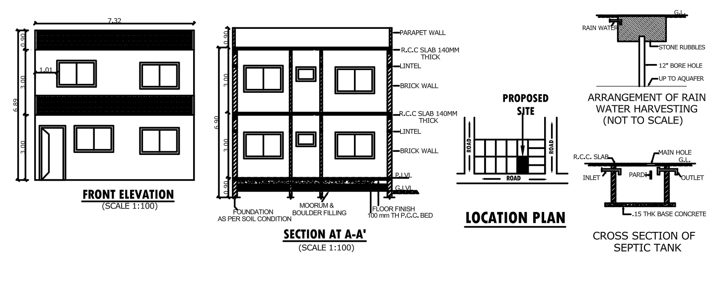
Building Section Drawing – Internal Vertical View
A section drawing cuts through the building vertically to reveal internal construction details.
This drawing cannot be understood from the plan alone, making it essential for approval.
What Does a Section Drawing Show?
Foundation depth.
PCC layer.
Footing.
Column.
Plinth level.
Damp Proof Course.
Floor height.
Beam depth.
Slab thickness.
Staircase section.
Roof slab.
Parapet height.
Ground level.
The section drawing clearly explains the building’s vertical relationship between all floors.
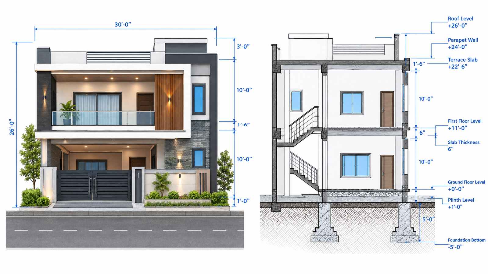
Why Section Drawings Matter
Section drawings help authorities verify:
Structural safety.
Building height.
Staircase design.
Floor-to-floor levels.
Foundation depth.
Roof construction.
Without section details, submission drawings often remain incomplete.
Foundation Plan – Base Layout of the Building
The foundation plan shows the structural base below ground level.
It is prepared after fixing the column grid and structural layout.
Information Included
Column positions.
Footing size.
Footing numbering.
PCC thickness.
Foundation dimensions.
Grid lines.
Centerline dimensions.
This drawing guides excavation and footing construction.
Column Layout Plan
The column layout defines the structural skeleton of the building.
Information Included
Column numbering.
Grid reference.
Column sizes.
Spacing between columns.
Structural center lines.
Proper column alignment ensures the load transfers safely to the foundation.
Beam Layout for G+1 House
The beam layout shows RCC beams connecting columns.
Important Beam Information
Beam numbering.
Beam size.
Beam direction.
Beam intersection with columns.
Lintel beams where required.
Beam drawings help structural engineers and site supervisors during construction.
Slab Layout Plan
The slab layout explains slab boundaries and slab thickness across the building.
Slab Drawing Includes
Slab panels.
Beam support.
Slab thickness.
Opening locations.
Stair opening.
Lift opening (if available).
This drawing becomes useful during reinforcement work.
Staircase Drawing – One of the Most Important Submission Drawings
A staircase drawing explains vertical movement inside the house.
Stair Drawing Should Mention
- Width of staircase.
Number of risers.
Tread size.
Landing size.
Stair direction.
Headroom clearance.
Railing position.
Floor levels.
A safe staircase design improves accessibility and complies with building standards.
Staircase Planning Guidelines
Good staircase planning includes:
Comfortable riser height.
Uniform tread width.
Adequate landing space.
Natural lighting where possible.
Safe railing height.
Proper staircase dimensions improve both safety and usability.
Door and Window Schedule
A submission drawing set usually contains a separate schedule listing every opening.
Purpose of Opening Schedule
Instead of writing dimensions repeatedly inside the plan, each opening receives a code.
Typical schedule information includes:
Door number.
Window number.
Ventilator number.
Width.
Height.
Quantity.
Material type.
This keeps drawings organized and easy to read.
Area Statement – Mandatory Calculation Sheet
Area calculation is an essential part of every submission drawing.
It explains how much of the plot is covered by construction and how much remains open.
Area Statement Includes
Plot Area.
Ground Coverage.
Ground Floor Built-up Area.
First Floor Built-up Area.
Total Built-up Area.
Balcony Area.
Terrace Area.
Parking Area.
FAR or FSI calculation.
Open Space Area.
Authorities compare these calculations with applicable building bye-laws.
Understanding Plot Area, Built-Up Area and FAR
Many beginners confuse these three terms.
Plot Area is the total land area available for construction.
Built-Up Area is the covered area measured along the outer walls of the building.
FAR/FSI defines the maximum construction area allowed on a plot according to local regulations.
Correct area calculations prevent approval objections.
Before starting construction, homeowners should understand the applicable approval requirements and documents. You can learn more about the building plan approval process in our detailed guide.
Setbacks in a G+1 Residential House
Setbacks are mandatory open spaces left around the building boundary.
These spaces provide ventilation, light, safety, and maintenance access.
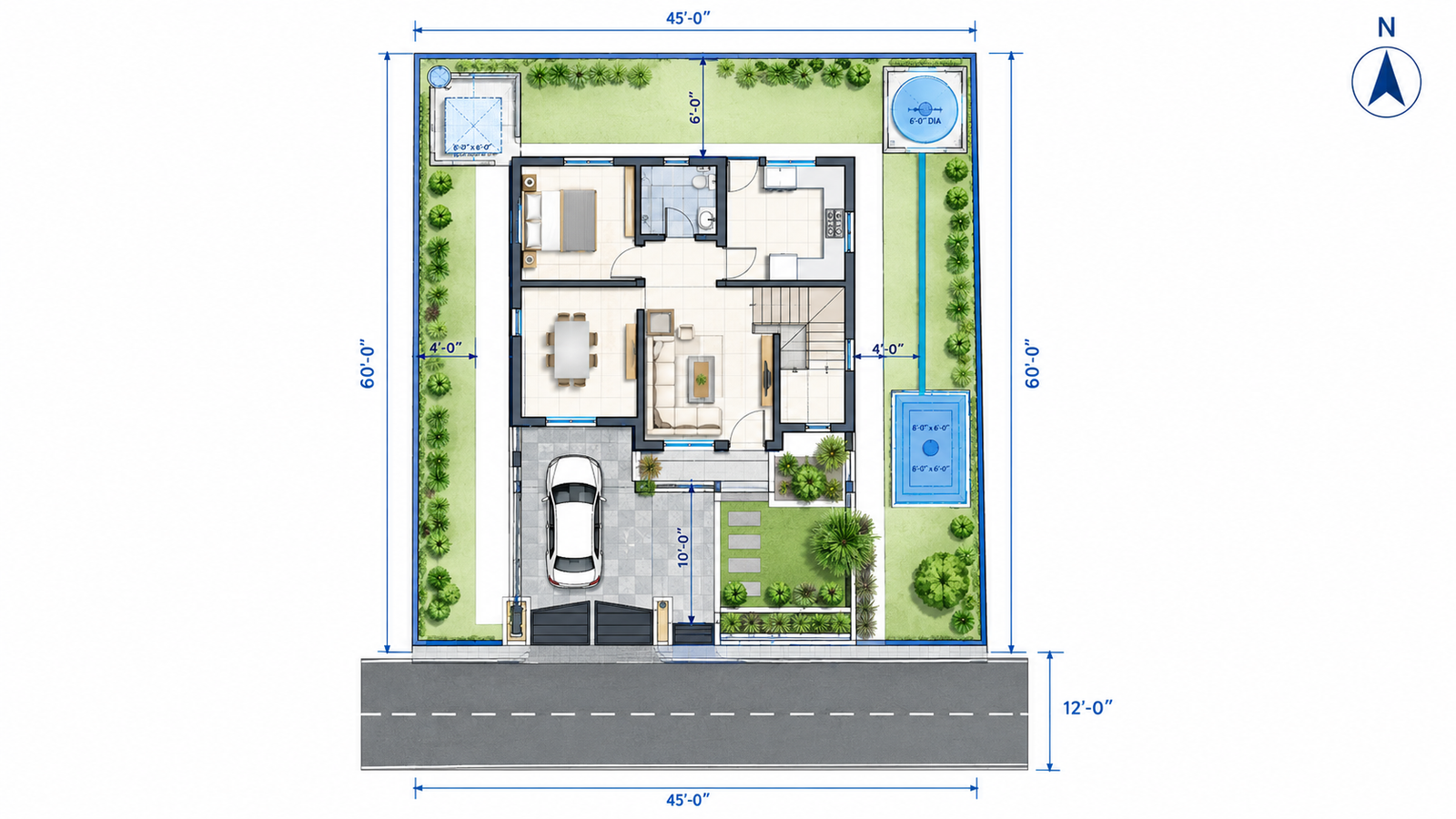
Common Types of Setbacks
Front setback.
Rear setback.
Left side setback.
Right side setback.
The required setback distance varies depending on plot size and local municipal rules.
Why Setbacks Are Important
Proper setbacks help ensure:
Natural light.
Ventilation.
Fire safety.
Access around the building.
Compliance with municipal bye-laws.
Incorrect setbacks are among the most common reasons for drawing revisions.
Levels Used in Submission Drawings
Building levels help contractors understand vertical construction dimensions.
Common Levels Mentioned
Natural Ground Level.
Finished Ground Level.
Plinth Level.
Ground Floor Level.
First Floor Level.
Terrace Level.
Roof Top Level.
Parapet Top Level.
Every level should be referenced from a common benchmark.
Construction Notes Included in Submission Drawings
Construction notes provide technical instructions applicable to the complete drawing set.
Typical notes mention:
All dimensions are in millimeters.
Do not scale drawings.
Verify dimensions on site.
RCC grade specification.
Brick wall thickness.
Foundation depth as per soil condition.
Follow structural engineer’s drawings.
Follow local building bye-laws.
These notes reduce confusion during execution.
Electrical Layout for a G+1 House
Some authorities request separate electrical drawings, while others accept them as supporting documents.
Electrical Drawing Includes
Switch boards.
Light points.
Fan points.
Power sockets.
AC points.
Distribution board.
Earthing location.
Meter position.
A proper electrical layout simplifies wiring during construction.
Plumbing Layout Drawing
Plumbing drawings explain water supply and wastewater flow.
Plumbing Layout Contains
Kitchen sink.
Wash basin.
Shower.
Toilet connection.
Soil pipe.
Waste pipe.
Water supply line.
Overhead tank connection.
Underground tank connection.
A coordinated plumbing layout avoids pipe clashes during construction.
Drainage and Rainwater Layout
Drainage drawings are increasingly important for residential approvals.
Drainage Drawing Includes
Rainwater pipes.
Inspection chambers.
Septic tank.
Soak pit.
Municipal sewer connection.
Stormwater outlet.
Proper drainage prevents waterlogging around the building.
Rainwater harvesting should also be considered during site planning. Government guidance and Model Building Bye-Laws include provisions for rainwater harvesting, although the exact requirements can vary according to local regulations.
Structural Drawings Required for G+1 House Approval
Architectural drawings explain the layout, while structural drawings explain how the building safely carries loads.
Structural Submission Includes
Column layout.
Footing details.
Beam layout.
Slab layout.
Stair reinforcement details.
Structural notes.
Many municipalities require structural drawings signed by a licensed structural engineer.
Standard Drawing Scales Used in Submission Drawings
Different drawings use different scales depending on the amount of detail required.
Generally:
Site plans use smaller scales to cover the complete plot.
Floor plans use larger scales for room dimensions.
Elevations and sections use scales suitable for height details.
Foundation details use detailed scales where structural clarity is required.
Maintaining a consistent scale improves drawing readability.
Before finalizing a G+1 layout, it is useful to compare different approaches to space planning, room arrangement and circulation. Explore our guide to modern house plans for additional planning ideas.
Title Block Details Every Drawing Should Include
Every submission sheet should contain a professional title block.
Title Block Information
Project title.
Drawing title.
Plot address.
Owner name.
Architect or engineer name.
License number.
Scale.
Drawing number.
Date.
Revision number.
North symbol.
A complete title block gives every sheet a professional appearance.
AutoCAD Layer Standards for Submission Drawings
Professional submission drawings become much easier to read when layers are properly managed.
Recommended Layer Organization
Separate layers for:
Walls.
Doors.
Windows.
Columns.
Dimensions.
Text.
Furniture.
Centerlines.
Hatch.
Plumbing.
Electrical.
Using organized layers makes editing faster and printing cleaner.
Line Weight Guidelines for Professional Drawings
Line weights help distinguish different building elements.
For example:
Thick lines for walls.
Medium lines for doors and windows.
Thin lines for dimensions.
Dashed lines for hidden elements.
Center lines for structural grids.
Proper line hierarchy improves drawing clarity.
Common Symbols Used in Submission Drawings
Submission drawings include standard architectural symbols so contractors and authorities understand the design quickly.
Important symbols include:
North direction.
Section line.
Elevation marker.
Grid line.
Level marker.
Door swing.
Window symbol.
Stair direction arrow.
Centerline.
Hatch pattern.
Using standard symbols improves communication.
Building Bye-Laws to Consider While Preparing Drawings
Every city follows its own development authority rules, but submission drawings generally need to comply with local building bye-laws regarding setbacks, building height, floor area ratio, parking provisions, ventilation, sanitation, and safety requirements. Always prepare drawings according to the regulations applicable in your city or development authority.
Documents Required Along With Submission Drawings
Drawings alone are not enough during the approval process.
Common supporting documents include:
Ownership documents.
Plot registry or sale deed.
Property tax receipt.
Identity proof.
Architect or engineer license copy.
Structural safety certificate.
Application form.
Soil report (where applicable).
NOC documents (if applicable).
Requirements vary between municipalities.
Step-by-Step Building Plan Approval Process
Understanding the approval workflow helps homeowners avoid unnecessary delays.
Step 1 – Site Survey
Measure the plot accurately and verify boundaries.
Step 2 – Prepare Architectural Design
Create floor plans, elevations, and sections.
Step 3 – Prepare Structural Drawings
Develop structural layouts based on architectural drawings.
Step 4 – Prepare Area Statement
Calculate built-up area, coverage, and FAR/FSI.
Step 5 – Submit Drawings
Submit the drawing set with required documents.
Step 6 – Municipal Verification
Authorities review setbacks, dimensions, and compliance.
Step 7 – Corrections if Required
Revise drawings if objections are raised.
Step 8 – Building Approval
Receive approved drawings before construction begins.
Following this sequence reduces approval delays.
Common Mistakes That Delay Building Approval
Many submission drawings are returned for corrections because of avoidable drafting mistakes.
Missing Site Information
An incomplete site plan without setbacks or north direction often leads to objections.
Incorrect Dimensions
Mismatched room dimensions, wall thickness, or plot measurements create approval issues.
Missing Section Drawing
Without a section drawing, authorities cannot verify building heights and foundation details.
Improper Area Calculations
Incorrect built-up area or FAR calculations may violate permissible limits.
Poor Drawing Presentation
Unreadable text, overlapping dimensions, and inconsistent line weights reduce drawing quality.
Always review drawings carefully before submission.
Tips to Prepare Professional G+1 Submission Drawings in AutoCAD
Creating submission drawings is not only about drawing walls—it is about presenting technical information professionally.
Use Accurate Units
Always work in millimeters for architectural drawings unless local standards require otherwise.
Keep Dimensions Clear
Place dimensions outside rooms wherever possible to improve readability.
Maintain Layer Discipline
Separate architectural, structural, plumbing, and electrical elements.
Use Proper Text Height
Ensure printed drawings remain readable on A1 or A2 sheets.
Verify Every Drawing Before Printing
Cross-check dimensions, room names, levels, and schedules before submission.
These small practices significantly improve drawing quality.
Who Can Prepare a G+1 Submission Drawing Set?
Different professionals contribute to the submission process.
Architects
Prepare architectural planning, elevations, sections, and presentation drawings.
Civil Engineers
Prepare structural layouts, foundation plans, and construction details.
Structural Engineers
Design columns, beams, slabs, and foundations based on structural calculations.
Homeowners
Can understand the drawing set and verify planning before submission, but approval generally requires drawings prepared or certified by licensed professionals according to local authority requirements.
Benefits of a Complete G+1 Submission Drawing Set
A professionally prepared drawing set offers several advantages:
Faster municipal approval.
Better construction planning.
Reduced site errors.
Clear communication with contractors.
Accurate quantity estimation.
Easier structural coordination.
Legal compliance with building regulations.
Professional documentation for future renovations.
A complete drawing set saves both time and construction cost.
Conclusion
A G+1 House Submission Drawing Set is much more than a floor plan—it is the complete technical documentation required to obtain building permission and execute construction confidently. It combines architectural planning, structural information, area calculations, elevations, sections, foundation details, and construction notes into one coordinated package.
Whether you are designing a duplex house, independent home, or residential bungalow, preparing accurate submission drawings according to local building bye-laws helps avoid approval delays and construction mistakes. A clean, well-organized drawing set also reflects professional drafting standards and makes the entire building process smoother from planning to execution.
Frequently Asked Questions
What is a G+1 house submission drawing?
A G+1 house submission drawing is a complete set of architectural and structural drawings submitted to local authorities for approval before constructing a Ground Floor plus First Floor residential building.
Which drawings are mandatory for G+1 building approval?
A complete submission set generally includes a site plan, ground floor plan, first floor plan, elevation, section drawing, foundation plan, area statement, opening schedule, and construction notes.
Why is a section drawing required in submission drawings?
A section drawing shows the internal vertical details of the building, including foundation depth, floor levels, slab thickness, staircase, roof level, and overall building height for approval verification.
What scale is commonly used for G+1 submission drawings?
Residential building plans, elevations, and sections are commonly prepared at 1:100, while detailed structural drawings may use larger scales depending on the drawing purpose.
Can I prepare submission drawings in AutoCAD?
Yes. AutoCAD is one of the most widely used software applications for preparing professional building submission drawings with accurate dimensions, layers, annotations, and printable layouts.