
Important Notes for Building Submission Drawings: Practical Guide for Architects
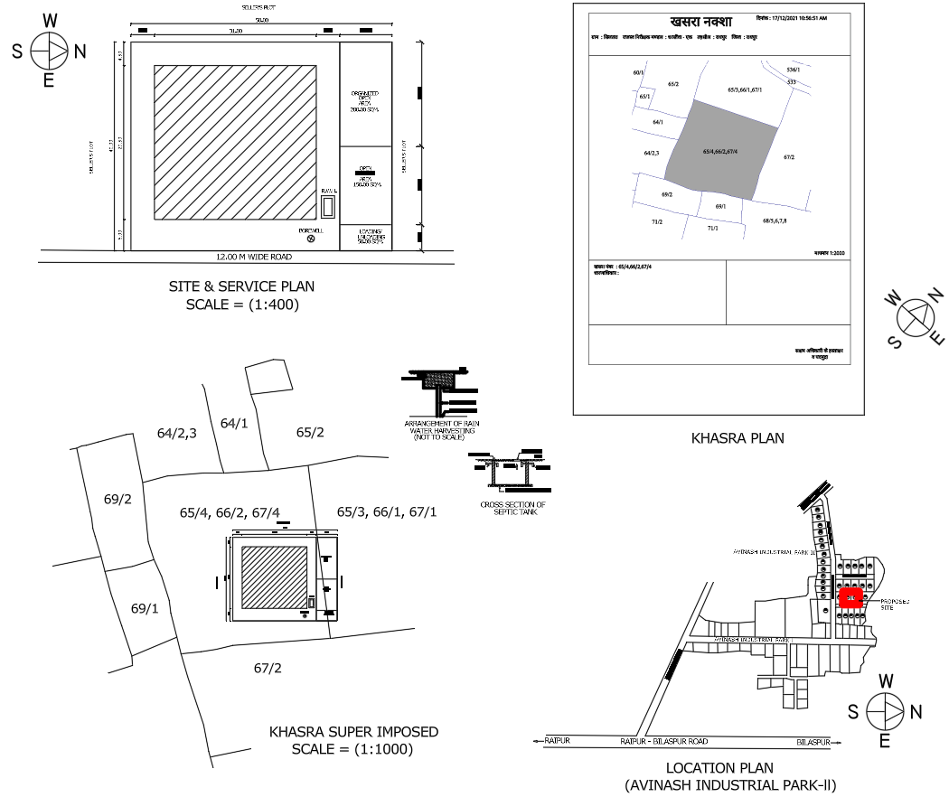
Building submission drawings are prepared to communicate a proposed building design to the concerned planning or building authority. Along with floor plans, elevations and sections, these drawings may contain technical notes that explain dimensions, levels, proposed construction, site conditions and other important design information.
A drawing may look complete but still leave questions unanswered if its notes are unclear, inconsistent or placed in the wrong location. For example, a floor plan may show a staircase, but its direction, level information or related dimensions may not be sufficiently clear. Similarly, a site plan may show a building outline without clearly identifying the relevant plot boundaries or setback distances.
The purpose of this guide is to explain which technical notes may be useful in building submission drawings, what each note communicates, and how to arrange them in an architectural drawing set.
Important: Drawing requirements differ between municipal corporations, development authorities, states and project types. Treat the examples below as drafting guidance, not as a universal list of mandatory notes. Always check the applicable local building regulations and submission requirements.
1. General Drawing Information
Every submission drawing sheet should identify the project and explain what the sheet represents. Without this information, it can become difficult to distinguish one drawing from another when several sheets are submitted together.
Depending on the authority’s prescribed format, the drawing title block may include:
- Project or building name.
- Site address or property identification.
- Name of the owner or applicant, where required.
- Drawing title, such as Ground Floor Plan or Section A–A.
- Drawing number and sheet number.
- Drawing scale.
- Date of preparation or revision.
- Name and registration details of the responsible professional, where applicable.
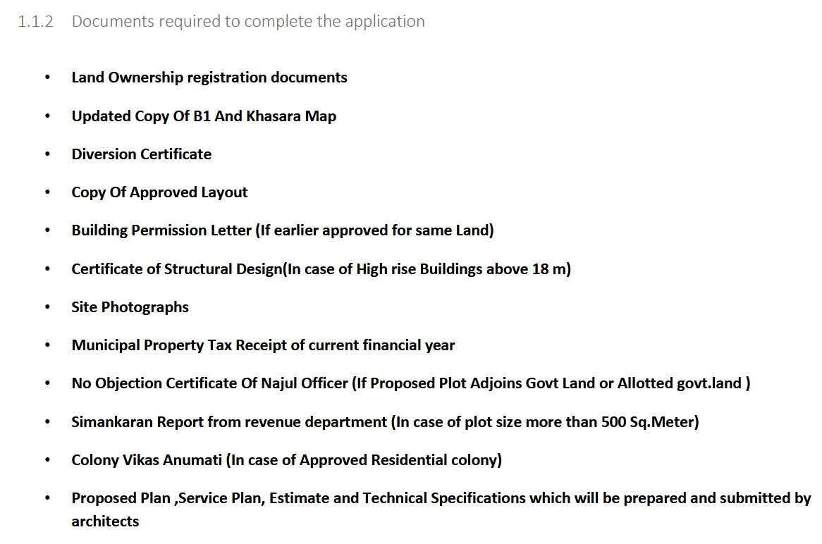
Example of a drawing identification note
Drawing Title: Proposed Ground Floor Plan
Drawing No.: A-02
Scale: 1:100
Revision: R01
Date: [Insert date]
These values are illustrative. Use the actual project information and the format prescribed by the relevant authority.
Keep the title block consistent across the drawing set. If the ground floor plan and first floor plan use different drawing numbers, their titles should still follow the same naming convention.
2. Plot Boundary and Site Information Notes
The site plan establishes the relationship between the proposed building and the property on which it will be constructed. Notes and labels on this drawing should make the site arrangement understandable without requiring the reader to guess what each line represents.
Depending on the project and local requirements, the site plan may identify:
- Plot boundaries and their dimensions.
- Plot number or property identification.
- Abutting road and road width.
- North direction.
- Existing structures and relevant site features.
- Proposed building footprint.
- Access or entry points.
- Required open spaces and setback dimensions.
- Relevant site levels and drainage information.
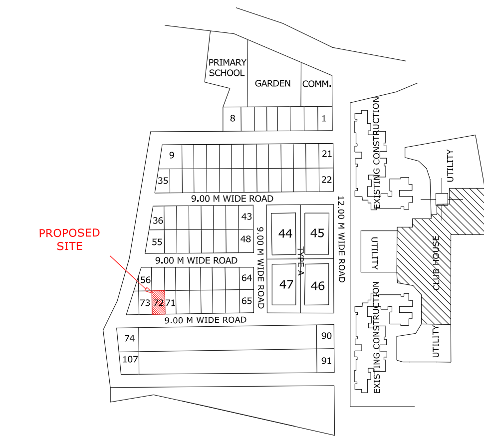
Example notes
- Plot Boundary: As per the verified site or property record.
- Abutting Road: [Insert verified road name and width].
- North Direction: Refer to the north arrow shown on the site plan.
- Existing Structure: Retained / proposed for removal, as applicable.
- Proposed Building: Refer to the building footprint shown on the drawing.
Do not insert assumed plot dimensions, road widths or property details. Confirm these details from reliable project records and the actual site information.
A useful drafting practice is to label existing and proposed features consistently. If the drawing uses different line types or colours to distinguish them, provide a legend where necessary.
3. Setback and Open Space Notes
Setback information communicates the distance between the building and the relevant plot boundaries. It is important because the building’s position must be checked against the applicable development controls.
The site plan should clearly identify the required setback dimensions wherever they apply. These may relate to the front, rear and side boundaries, depending on the plot, road conditions, building type and local rules.
Setback dimensions and open spaces should be checked against the regulations applicable to the project location. For more information, read our guide on Building Plan Approval Rules and Bye-Laws.
Setback dimensions and open space requirements should be verified according to the applicable local building regulations. Refer to the Model Building Bye-Laws and planning guidelines for general guidance, and check the rules prescribed by the concerned local authority.
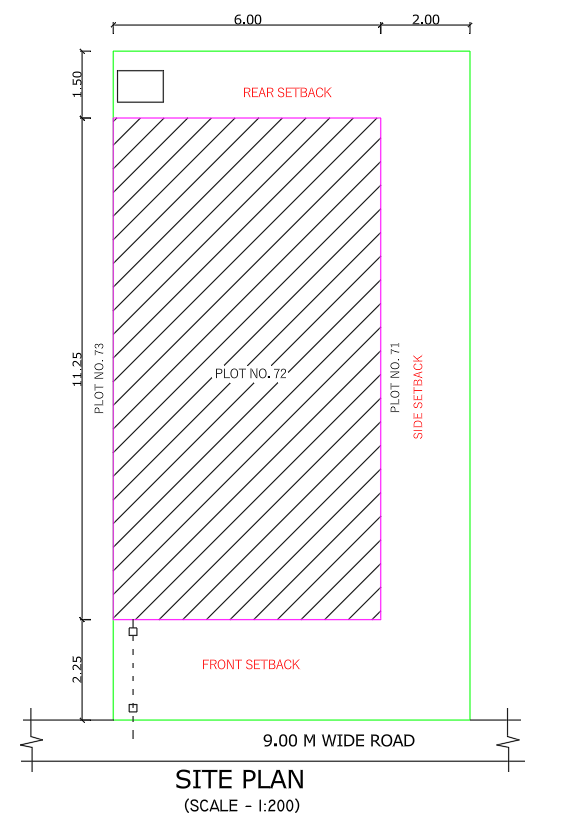
Example notes
- Front Setback: [Insert verified dimension].
- Rear Setback: [Insert verified dimension].
- Left Side Setback: [Insert verified dimension].
- Right Side Setback: [Insert verified dimension].
These are sample labels, not standard setback values. Do not use the same setback dimensions for every project.
What should be checked?
Confirm that the dimensions refer to the correct building face and property boundary. Where a building has projections, balconies, steps or other elements that affect the required open space, check how the applicable regulations treat those elements.
Avoid showing a setback dimension in one place and a different value in another. If a building position changes during revision, update the affected dimensions and area calculations as well.
4. Floor Plan Dimensions and Room Labels
Floor plans communicate the internal arrangement of the building. Their notes should make room use, dimensions and circulation clear.
Depending on the drawing’s purpose, useful information may include:
- Room names.
- Room dimensions.
- Wall thicknesses where relevant.
- Door and window identification.
- Staircase direction and configuration.
- Kitchen, bathroom and toilet locations.
- Entrance and circulation spaces.
- Floor level information, where required.
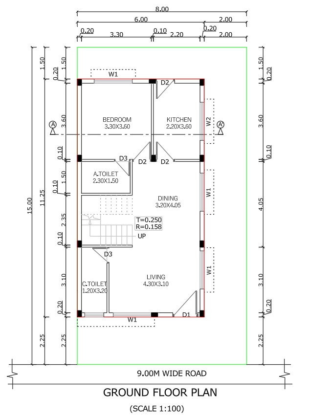
Example room labels
- Living Room
- Bedroom 01
- Kitchen
- Toilet
- Staircase
- Balcony
- Utility Area
Use room names that accurately describe the proposed use. Avoid adding labels that conflict with the actual layout.
Dimensioning practice
Dimensions should be readable and should clearly identify what is being measured. Use a consistent dimension style throughout the drawing set.
For example, if a room is shown as 3.60 m × 3.00 m, confirm that the dimensions correspond to the intended measurement points and that the drawing’s unit convention is clear.
Do not rely only on measuring a printed drawing. The written dimensions and the actual design information should agree.
5. Floor Levels and Building Height Notes
Levels explain the vertical relationship between floors, entrances, roads and other relevant building elements. They are especially useful when the site is sloping or when the proposed plinth level differs from the adjacent road level.
Depending on the project, the drawings may identify:
- Existing ground level.
- Proposed ground level.
- Plinth level.
- Finished floor level.
- First floor level.
- Terrace or roof level.
- Parapet level.
- Overall building height.
Example level labels
- Ground Floor FFL: [Insert verified level].
- First Floor FFL: [Insert verified level].
- Terrace Level: [Insert verified level].
- Proposed Plinth Level: [Insert verified level].
FFL means Finished Floor Level.
Use a consistent datum or reference level wherever required. The level values must be based on the actual design and site information, not copied from an unrelated drawing.
Building height should be calculated and labelled according to the definition used in the applicable local regulations. The point from which height is measured and the elements included in the measurement can vary.
6. Elevation Drawing Notes
Elevation drawings show the exterior appearance and vertical proportions of a building. Their notes should clarify important heights, levels and visible building elements.
Depending on the authority’s requirements, an elevation may include:
- Ground or plinth reference level.
- Floor-to-floor levels.
- Roof or terrace level.
- Parapet height.
- Door and window positions.
- Balcony or projection details.
- Overall building height.
- Exterior finish information, where requested.
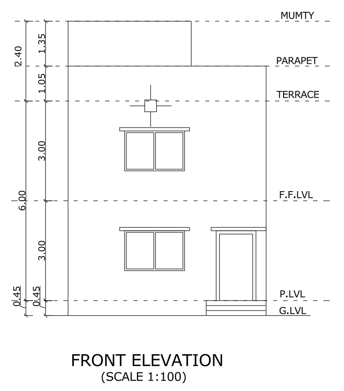
Example notes
- Front Elevation
- Proposed Plinth Level
- First Floor Level
- Terrace Level
- Parapet Level
- Overall Height: [Insert verified value]
Check that the levels and openings shown in the elevation agree with the corresponding floor plans and sections.
For example, if a window is moved in the floor plan, the elevation should be revised to reflect the same change. A note cannot compensate for a mismatch between drawings.
7. Section Drawing Notes
A building section explains vertical construction and spatial relationships that may not be clear in a plan or elevation.
Depending on the project and submission requirements, a section may identify:
- Ground and floor levels.
- Floor-to-floor heights.
- Room heights.
- Staircase arrangement.
- Roof and terrace levels.
- Plinth level.
- Relevant wall, slab or roof information.
- Basement levels, where applicable.
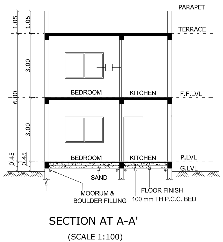
Example section labels
- Section A–A
- Ground Floor Level
- First Floor Level
- Terrace Level
- Staircase
- Roof Slab
- Proposed Plinth Level
Use section references that correspond to the cutting lines shown on the relevant floor plans.
If a section passes through the staircase, kitchen, toilet or another important area, make sure the section actually represents the intended cut through that part of the building.
Do not include structural sizes or construction specifications unless they are supported by the relevant design information and are appropriate for the submission drawing.
8. Area Statement and Calculation Notes
Area calculations are a common source of inconsistency between architectural drawings. The site plan, floor plans and area statement should use the same verified project data and the definitions required by the local authority.
Depending on the project, the area statement may include:
- Plot area.
- Ground coverage.
- Floor area for each floor.
- Total floor area.
- Permissible and proposed FAR/FSI.
- Parking area or parking calculations.
- Other area categories required by the authority.
FAR is commonly used to describe the relationship between the relevant floor area and plot area. However, the exact method of calculating the floor area and permissible FAR depends on the applicable regulations.
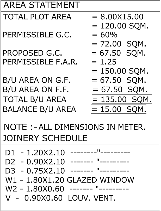
Example area statement
Plot Area: [Insert verified plot area]
Ground Floor Area: [Insert calculated area]
First Floor Area: [Insert calculated area]
Total Counted Floor Area: [Insert calculated area]
Ground Coverage: [Insert calculated percentage]
Proposed FAR/FSI: [Insert calculated value]
Note: Use verified project dimensions and calculate areas according to the applicable local building regulations.
A practical checking method
First, verify the plot area. Next, calculate the relevant building areas using the definitions prescribed by the authority. Then compare the totals with the floor plans and site plan.
If a balcony, stairwell, parking space or other element is treated differently under the applicable rules, do not assume that it must be included or excluded in every calculation. Follow the specific local definition.
9. Water Supply, Drainage and Service Notes
Building drawings may need to identify the proposed arrangement for essential services. The level of detail depends on the building, the submission stage and the authority’s requirements.
Relevant information may include:
- Water supply arrangements.
- Water storage tank or sump location.
- Sanitary fixtures and drainage connections.
- Sewer connection or approved disposal arrangement.
- Rainwater drainage.
- Rainwater harvesting provisions, where applicable.
- Septic tank or soak pit, where permitted and required.
- Relevant service lines and inspection chambers.
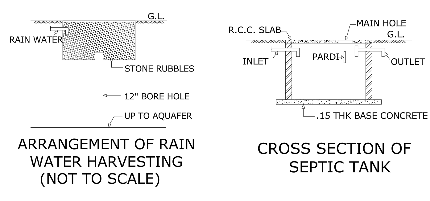
Example notes
- Water Storage: Refer to the service layout.
- Sanitary Drainage: Refer to the proposed drainage arrangement.
- Rainwater Management: As per the applicable requirements.
- Service Connection: Subject to the approved utility arrangement.
These notes should describe the actual proposed design. Do not state that a service is approved or connected if that has not been established.
Where detailed service drawings are required, provide the necessary information in the relevant drawing rather than relying on a short general note.
10. Parking and Access Notes
Parking and access information helps reviewers understand how vehicles and pedestrians will enter and move through the site.
Where applicable, the drawings may identify:
- Parking spaces and their dimensions.
- Number and type of proposed parking spaces.
- Vehicle entry and exit.
- Driveway arrangement.
- Pedestrian access.
- Ramps and circulation paths.
- Accessible parking and access provisions, where required.
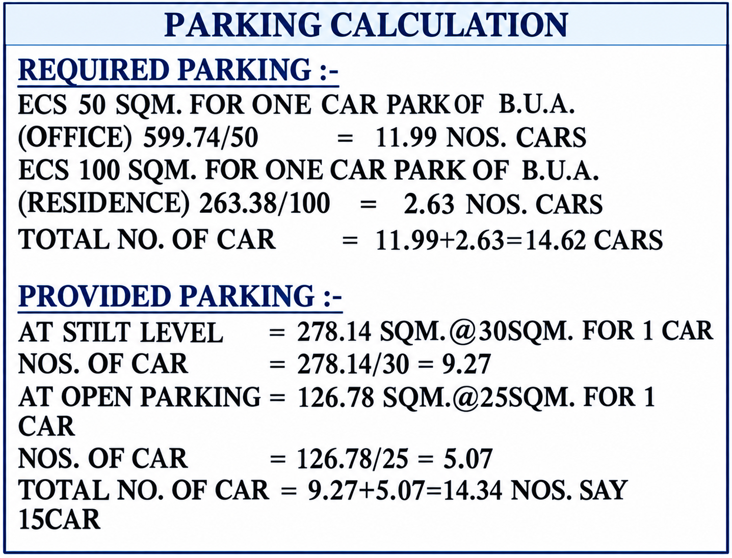
Example notes
- Proposed Parking: [Insert verified number and arrangement].
- Vehicle Entry: Refer to the site plan.
- Driveway Width: [Insert verified dimension].
- Ramp Details: Refer to the relevant drawing.
Check the parking arrangement against the actual plot layout. A parking space should not be counted merely because a rectangle has been drawn; its usable dimensions, access and compliance with applicable rules must also be checked.
11. Notes for Existing Buildings and Proposed Alterations
For additions, alterations or renovation projects, the drawing should distinguish between existing construction, work to be retained, work to be removed and proposed new work.
This distinction helps prevent confusion about the scope of the application.
Where required, include:
- Existing construction to be retained.
- Existing construction proposed for removal.
- Proposed new construction.
- Revised room arrangement.
- Relevant existing levels.
- A legend explaining the drawing conventions.
Example notes
Existing Construction: Structure to be retained.
Proposed Construction: New construction to be added.
Demolition Work: Existing construction proposed for removal.
Plot Boundary: Boundary of the property.
Building Line: Outline of the proposed building.
Dimension Line: Indicates measurements and distances.
Section Line: Shows the location and direction of a building section.
Note: Use the line types, symbols and colours prescribed by the concerned building authority.
12. General Notes and Professional Responsibility
General notes should clarify the scope and interpretation of the drawing. They should not be used as a substitute for missing dimensions, calculations or regulatory checks.
Depending on the project and local requirements, general notes may cover:
- Units of measurement.
- Drawing scale and print requirements.
- Reference drawings.
- Revision identification.
- Coordination with related drawings.
- Verification of site information.
- Responsibility for design and certification.
Building drawings should be prepared with due consideration to applicable building safety and technical requirements. Refer to the National Building Code of India as a technical reference, along with the current regulations and submission requirements applicable to the project.
Example general notes
- All dimensions shall be read in the units stated on the drawing.
- Written dimensions shall take precedence over scaling the drawing, subject to the applicable drawing instructions.
- Any discrepancy between related drawings shall be referred to the responsible professional for clarification before the affected work proceeds.
- Site dimensions and existing conditions shall be verified against reliable project information.
- All work shall comply with the applicable approved drawings and relevant statutory requirements.
Adapt these statements to the purpose of the drawing. Do not use general notes to transfer professional responsibilities improperly or to override applicable legal requirements.
13. How to Arrange Notes in an AutoCAD Drawing
A well-arranged drawing allows the reviewer to locate the required information quickly. The goal is not to fill every empty space with text, but to make the drawing clear and readable.
For better drawing organization, use separate layers for notes, dimensions, room labels and symbols. Read our guide on AutoCAD Layer Standards for Professional Submission Drawings to understand how drawing elements can be organized more consistently.
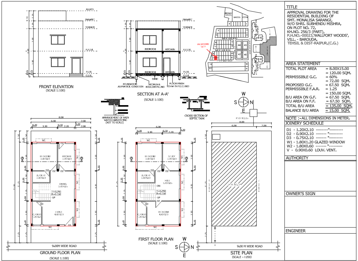
Step 1: Identify the drawing type
Decide whether you are preparing a site plan, floor plan, elevation, section or area statement. Each drawing requires different information.
For example, plot boundaries and setbacks are primarily associated with the site plan, while floor levels and overall height are commonly shown in elevations and sections.
Step 2: Create a dedicated notes area
Place general notes in a consistent location where they do not cover important drawing information. Keep drawing-specific labels close to the feature they describe.
Avoid placing notes directly over dimensions, room names or building outlines.
Step 3: Use consistent text and dimension styles
Create suitable text and dimension styles in AutoCAD. Check the final plotted sheet to make sure the text is readable at the intended print size.
The appropriate text height depends on the sheet size, plotting scale and authority’s submission requirements. There is no single text height that is suitable for every drawing.
Step 4: Organize notes using layers
Separate text, dimensions, room labels, symbols and other drawing elements into logical layers where practical. This makes the drawing easier to edit and review.
For example, a drawing may use separate layers for general notes, room names, dimensions and level symbols. Use a naming system that is consistent throughout the project.
Step 5: Check the plotted drawing
Review the PDF or printed sheet rather than relying only on the model-space view. Look for text that is too small, overlapping leaders, cut-off notes, unclear symbols and inconsistent line weights.
A note that appears readable on a large computer screen may be difficult to read on the final submitted sheet.
14. Common Problems with Submission Drawing Notes
Missing or unclear units
A dimension without a clear unit convention can be misinterpreted. State the drawing units as required and use them consistently.
Conflicting dimensions
If two dimensions describe the same distance but show different values, the reviewer may not know which one represents the intended design. Verify the geometry and update the dimensions.
Incorrect level references
Levels should use a consistent reference system. Check that the plinth, floor, terrace and height information agrees across the relevant drawings.
Outdated area calculations
When the building footprint or floor layout changes, related area calculations may also change. Recalculate the affected values instead of updating only the drawing geometry.
Unclear existing and proposed work
Too many notes in a small area can make a drawing difficult to read. Group related information, use clear headings and remove redundant labels.
Unverified regulatory statements
Avoid copying setback, FAR, height or parking values from another project. Verify the applicable rules for the specific location and building type.
15. Final Review Before Submitting the Drawing
Before issuing the drawing set, review the following points:
- Project identification and drawing numbers are consistent.
- Plot dimensions and site information have been verified.
- Setback dimensions correspond to the proposed building position.
- Room labels and dimensions match the actual plan.
- Floor levels and building height are coordinated.
- Elevations and sections agree with the floor plans.
- Area calculations use the relevant local definitions.
- Parking and service arrangements match the proposed layout.
- Existing and proposed work are clearly distinguished where applicable.
- Notes are readable in the final PDF or print.
- Required signatures, certifications and other prescribed details are included.
- The drawing set follows the relevant authority’s current submission format.
This review is a drafting quality-control step, not a guarantee of approval. The concerned authority may require additional drawings, documents or corrections.
Along with correctly prepared drawings, applicants may need supporting documents according to the local authority’s requirements. See our guide to Documents Required for Building Plan Approval in India for further details.
Conclusion
Technical notes are an important part of a clear building submission drawing. They explain dimensions, levels, building areas, site arrangements and other details that may not be immediately obvious from the drawing geometry alone.
For architects and AutoCAD users, the most useful practice is to place each note where it supports the relevant drawing, keep related information consistent and verify the final plotted sheet. Most importantly, use project-specific values and follow the applicable local building regulations instead of copying standard notes without checking them.
A well-coordinated drawing set is easier to read, revise and review, and it reduces avoidable confusion during the submission process.