
Residential Building Submission Drawing: What to Include in a Complete Drawing Set
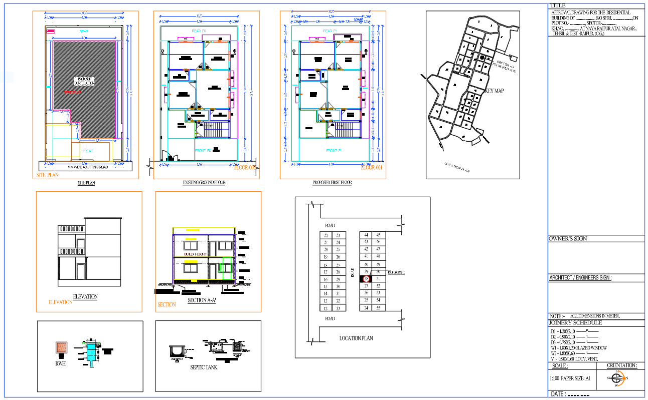
A residential building does not move directly from an idea to construction. Before work begins, the proposed design usually needs to be represented through a clear set of drawings and supporting information. These drawings allow the proposed building to be understood in terms of its site position, floor arrangement, height, access, open spaces, and other planning information required by the concerned authority.
A residential building submission drawing is therefore more than a floor plan. It is a coordinated drawing set in which different sheets explain different aspects of the proposed building.
The exact drawings, formats, scales, documents, and submission requirements can vary according to the location and the authority responsible for building permissions. For an actual project, the applicable local rules should always be checked before preparing the final submission.
This guide explains how a residential submission drawing set is generally organized, what each drawing communicates, how the sheets should relate to one another, and what should be checked before submission.
What Is a Residential Building Submission Drawing?
A residential building submission drawing is a collection of architectural and planning drawings prepared to communicate a proposed residential development to the relevant authority.
Instead of showing the building from only one viewpoint, the drawing set presents the proposal from several directions.
For example:
- The site plan explains where the building sits on the plot.
- The floor plan explains the arrangement of spaces on each level.
- The elevation shows the external vertical appearance.
- The section explains important vertical relationships.
- The area statement summarizes relevant area calculations.
- Additional drawings may be included when required for a particular project or authority.
The purpose of combining these drawings is to create a consistent representation of the proposed building.
A change made to one drawing may sometimes require changes in another. For example, changing the building footprint can affect the site plan, floor plan, area calculations, setbacks, and elevations.
That is why a submission drawing set should be treated as one coordinated package rather than a collection of unrelated sheets.
Why Is a Submission Drawing Set Important?
A properly organized drawing set helps different people understand the same building proposal.
For the authority, it provides information needed to examine the proposal against applicable planning and development requirements.
For the designer, coordinated drawings help identify inconsistencies before the documents are finalized.
For the property owner, the drawings provide a clearer picture of what is being proposed.
A good submission set should make important information easy to locate rather than forcing the reader to interpret an unclear or incomplete drawing.
The quality of a submission drawing is therefore not determined only by how attractive the sheet looks. Accuracy, clarity, consistency, and completeness are much more important.
For a detailed explanation of the approval procedure, documents, and submission stages, read our guide to the Building Plan Submission Process.
Main Drawings Used in a Residential Submission Set
The exact contents differ between projects and authorities, but a residential submission package commonly revolves around several important drawing types.
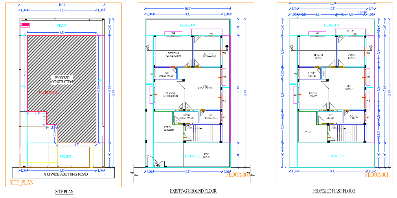
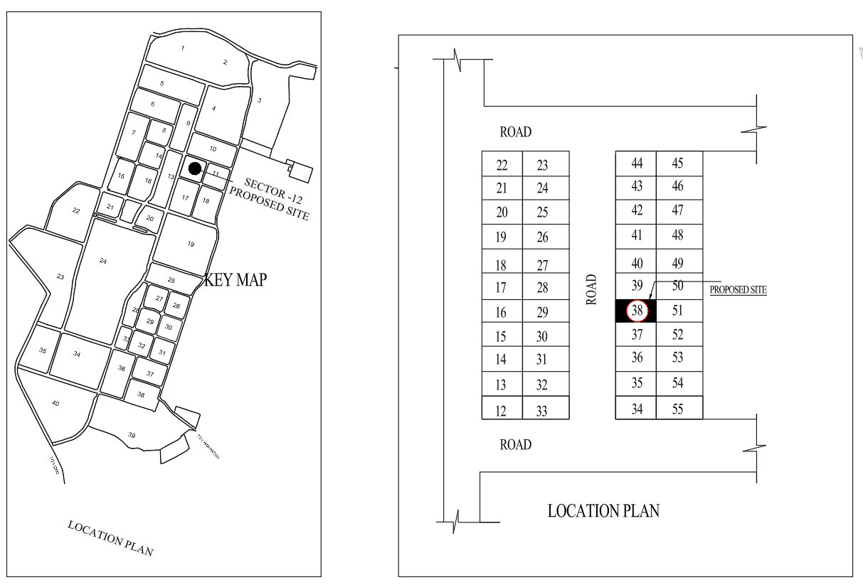
1. Site Plan
The site plan establishes the relationship between the proposed building and the property around it.
Unlike a floor plan, which focuses mainly on the building layout, the site plan looks at the building as part of the entire plot.
A residential site plan may communicate:
- Plot boundary
- Plot dimensions
- Existing or proposed road
- North direction
- Building footprint
- Required open spaces
- Front, rear, and side setbacks
- Entrance and access
- Parking arrangement
- Adjacent properties
- Other site features where applicable
The site plan is particularly important because the building cannot be evaluated independently from its plot.
For example, a floor plan may appear suitable when viewed by itself, but the same design may require modification if the proposed footprint does not maintain the required open spaces around the property.
What to check in a site plan
Before finalizing the sheet, check whether:
- The plot boundary is clearly identifiable.
- Plot dimensions are readable.
- North direction is correctly indicated.
- The building footprint matches the floor plan.
- Setback dimensions are consistent.
- Entry and access points are clearly shown.
- Parking is represented correctly where applicable.
- Adjacent road information is clear.
2. Ground Floor Plan
The ground floor plan explains how the proposed spaces are arranged at ground level.
Depending on the project, it can show rooms such as:
- Living room
- Dining area
- Kitchen
- Bedrooms
- Toilets
- Staircase
- Utility areas
- Verandah
- Parking or covered areas
A submission-oriented floor plan should communicate the planning information clearly rather than focusing only on presentation.
Important information may include room names, dimensions, wall positions, openings, staircase arrangement, and other information required by the applicable submission standard.
Why coordination matters
The ground floor plan should agree with the site plan.
For example, if the site plan shows the building beginning at a particular setback distance, the floor plan should represent the same building footprint.
Similarly, the staircase, entrance, parking access, and external projections should be checked across the relevant drawings.
4. Roof or Terrace Plan
Where required, a roof or terrace plan provides information about the uppermost level of the building.
Depending on the project, it may identify:
- Staircase headroom
- Parapet
- Terrace area
- Water tank
- Roof access
- Solar equipment
- Rainwater-related features
- Roof drainage arrangements
The purpose of this sheet is not simply to show the top of the building. It helps explain how the roof level is organized and how it relates to the rest of the proposal.
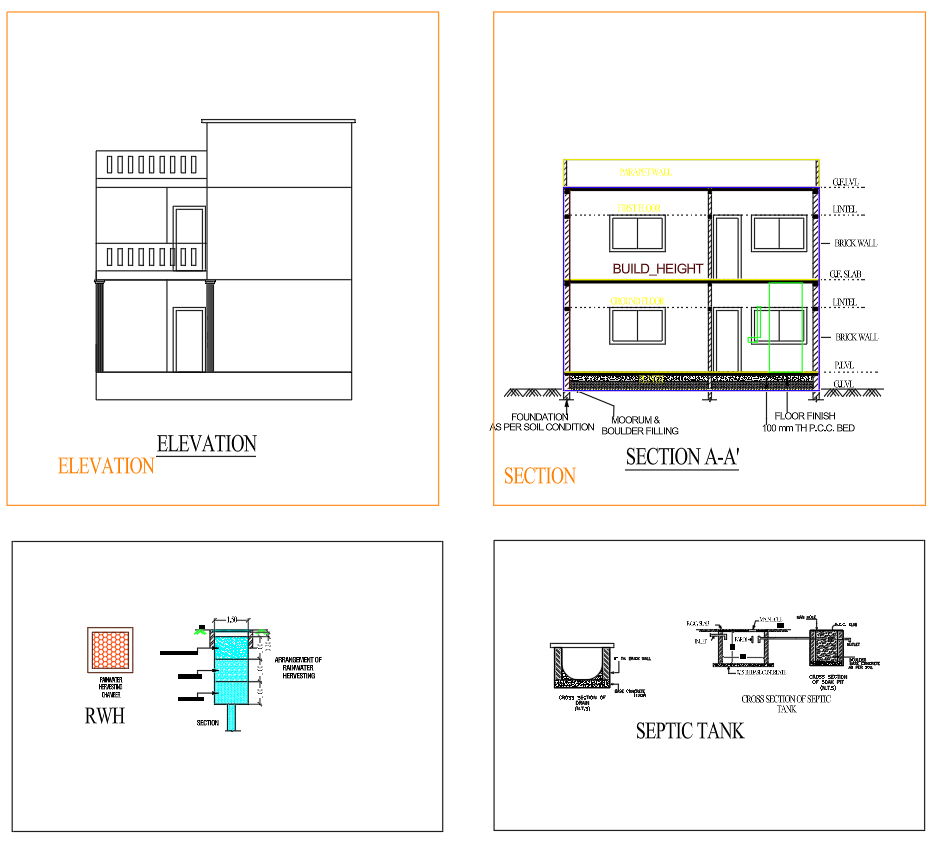
5. Building Elevation
An elevation represents the building as viewed from the outside.
A residential submission set may contain a front elevation and, where necessary, additional side or rear elevations.
An elevation can communicate:
- Overall building height
- Number of floors
- Floor levels
- Doors and windows
- Balcony positions
- Parapet
- Roof profile
- External projections
- Exterior elements
For submission purposes, the elevation should be consistent with the floor plans and sections.
For example, if a window is shown at a particular location on the elevation, its position should make sense when compared with the corresponding floor plan.
The elevation should not be treated as a completely separate drawing.
6. Building Section
A section is one of the most useful drawings for understanding the vertical arrangement of a building.
Imagine the building being cut vertically so that its internal construction levels can be viewed.
A typical building section can help explain:
- Ground level
- Plinth level
- Floor levels
- Floor-to-floor height
- Staircase arrangement
- Slab levels
- Ceiling relationship
- Roof level
- Parapet height
- Vertical openings
Sections become particularly useful when the building has multiple floors or changes in floor levels.
A section should correspond with the floor plans and elevation. If the floor-to-floor height or staircase arrangement shown in the section conflicts with another drawing, the set needs to be reviewed before submission.
7. Area Statement
An area statement summarizes important calculations associated with the proposed development.
Depending on the local submission requirements, it may include items such as:
- Plot area
- Ground coverage
- Built-up area
- Floor-wise area
- Total proposed area
- Open area
- Parking area
- Other applicable area calculations
The exact terminology and calculation method can differ between authorities.
The important point is that the figures should be derived from the actual drawing and should remain consistent throughout the submission set.
An area statement should not be treated as an isolated table prepared at the end. Changes to the plan can affect the calculated areas, so the figures should be rechecked whenever the design changes.
6. Building Section
A section is one of the most useful drawings for understanding the vertical arrangement of a building.
Imagine the building being cut vertically so that its internal construction levels can be viewed.
A typical building section can help explain:
- Ground level
- Plinth level
- Floor levels
- Floor-to-floor height
- Staircase arrangement
- Slab levels
- Ceiling relationship
- Roof level
- Parapet height
- Vertical openings
Sections become particularly useful when the building has multiple floors or changes in floor levels.
A section should correspond with the floor plans and elevation. If the floor-to-floor height or staircase arrangement shown in the section conflicts with another drawing, the set needs to be reviewed before submission.
For a more detailed explanation of section drawings, including levels, heights, and important information to show, see our guide on Section Drawing for Building Submission.
7. Area Statement
An area statement summarizes important calculations associated with the proposed development.
Depending on the local submission requirements, it may include items such as:
- Plot area
- Ground coverage
- Built-up area
- Floor-wise area
- Total proposed area
- Open area
- Parking area
- Other applicable area calculations
The exact terminology and calculation method can differ between authorities.
The important point is that the figures should be derived from the actual drawing and should remain consistent throughout the submission set.
An area statement should not be treated as an isolated table prepared at the end. Changes to the plan can affect the calculated areas, so the figures should be rechecked whenever the design changes.
8. Parking and Access Information
Parking can be an important part of residential planning, particularly where the authority has specific parking requirements.
The drawing may need to communicate:
- Vehicle parking position
- Parking dimensions
- Driveway or access
- Entry and exit arrangement
- Ramp information where applicable
- Relationship between parking and the building entrance
The available parking area should be practical rather than simply fitting a rectangle labeled “parking.”
Vehicle movement, door opening space, pedestrian access, and connection to the main entrance should also be considered during planning.
9. Open Spaces and Setbacks
Open spaces around a building are an important part of residential site planning.
Setbacks may be required to provide separation between the building and property boundaries, roads, or neighboring properties.
The required dimensions are not universal. They can depend on factors such as:
- Location
- Plot characteristics
- Building height
- Road width
- Development regulations
- Local authority requirements
Therefore, designers should not use a single standard setback value for every residential project.
The applicable local regulations should be checked before the drawing is finalized.
Building requirements can vary from one location to another. For additional reference, readers can review the Standardized Development and Building Regulations published by the Bureau of Indian Standards and then verify the applicable rules with their local authority.
10. Supporting Information and Additional Drawings
Some residential projects require information beyond the basic architectural sheets.
Depending on the project and authority, additional material may include:
- Ownership-related documents
- Application forms
- Professional certification
- Structural information
- Service-related drawings
- Site photographs
- Special calculations
- Other supporting documents
The exact requirements should be confirmed with the concerned authority.
This is important because a checklist suitable for one city or authority may not automatically apply to another.
How the Different Drawings Work Together
One of the most important aspects of a submission set is coordination.
Each drawing describes the same building from a different viewpoint.
Consider a simple example.
Suppose a G+1 house has:
- A staircase near the center of the plan
- A balcony on the first floor
- A specific building height
- A defined front setback
The staircase should appear consistently in the relevant floor plans and section.
The balcony should correspond with the floor plan and elevation.
The building height shown in the elevation should be compatible with the section.
The building footprint shown in the site plan should correspond with the floor plan.
This coordination is what turns several individual drawings into a reliable drawing set.
A Practical Workflow for Preparing a Submission Drawing Set
A simple workflow can reduce mistakes during drawing preparation.
If you want to learn the actual AutoCAD workflow for preparing submission drawings, see our detailed guide on How to Create Submission Drawings in AutoCAD.
Step 1: Collect Site Information
Start with the available site information, including plot dimensions, road position, orientation, and other relevant site conditions.
Step 2: Establish the Building Footprint
Determine the proposed building area after considering the applicable planning restrictions and open spaces.
Step 3: Develop the Floor Plans
Prepare the required floor layouts and check room arrangement, circulation, access, openings, and staircase placement.
Step 4: Prepare the Site Plan
Place the building footprint accurately within the plot and add the required site information.
Step 5: Develop Elevations
Prepare the external views based on the coordinated floor plans.
Step 6: Prepare Sections
Select appropriate section lines that explain important vertical relationships.
Step 7: Calculate Areas
Prepare the required area information from the finalized or sufficiently coordinated plans.
Step 8: Coordinate the Sheets
Compare the plans, site drawing, elevation, section, and area information.
Step 9: Perform a Final Check
Check dimensions, labels, drawing titles, orientation, scale, sheet numbering, and other project-specific requirements before submission.
Common Problems Found in Residential Submission Drawings
Many drawing problems are not caused by difficult design concepts. They happen because different sheets are not updated together.
1. Different dimensions on different sheets
A building dimension shown in the floor plan should not unexpectedly differ from the corresponding information elsewhere.
2. Site plan and floor plan do not match
The building footprint, entrance, or projections may be shown differently.
3. Incorrect area calculations
A design change may occur after the area statement is prepared, leaving outdated figures.
4. Missing drawing information
Important labels, dimensions, levels, orientation, or other required information may be absent.
5. Unclear drawing presentation
Overlapping dimensions, unreadable text, excessive linework, or poor sheet organization can make a technically correct drawing difficult to interpret.
6. Elevation does not match the plan
Doors, windows, balconies, or projections may appear differently between the drawings.
7. Section does not represent the actual design
Floor levels, staircase arrangements, or building heights may not correspond with the plan.
8. Using generic rules without checking local requirements
A common mistake is assuming that one set of building rules applies everywhere.
Building permission requirements can vary by authority, so project-specific verification is essential.
Drawing Scale, Sheet Layout, and Presentation
A technically correct drawing can still be difficult to use if the sheet is poorly organized.
Before finalizing the submission sheets, pay attention to:
Drawing scale
Use the scale required or accepted by the relevant authority and make sure the printed drawing remains readable.
Title block
Include appropriate project and drawing information such as drawing title, project identification, scale, date, sheet number, and professional details where required.
North direction
The orientation should be clearly visible wherever it is relevant.
Dimensioning
Dimensions should be readable and should not unnecessarily overlap walls, text, symbols, or other dimensions.
Line hierarchy
Different line weights can help distinguish major building elements, openings, dimensions, and supporting information.
Sheet numbering
A consistent numbering system makes the drawing package easier to review and reference.
Good presentation does not replace technical accuracy, but it makes accurate information much easier to understand.
For additional reference on residential building documentation and design-related publications, readers can explore the CPWD publications available from the Central Public Works Department.
How to Check a Submission Drawing Before Finalizing It
A final review should be carried out before the drawing set is issued.
Site check
- Plot dimensions checked
- Road position checked
- North direction checked
- Building location checked
- Setbacks checked
Plan check
- Room names checked
- Dimensions checked
- Doors and windows checked
- Staircase checked
- Floor levels checked
Elevation check
- Building height checked
- Openings checked
- Balconies and projections checked
- Floor levels coordinated
Section check
- Floor-to-floor levels checked
- Plinth checked
- Staircase checked
- Roof level checked
Area check
- Plot area checked
- Floor areas checked
- Total proposed area checked
- Other applicable calculations checked
Sheet check
- Drawing title checked
- Scale checked
- North arrow checked where applicable
- Sheet number checked
- Notes and labels checked
- Printing readability checked
This final review can catch small inconsistencies before they become larger documentation problems.
Important Note About Local Building Regulations
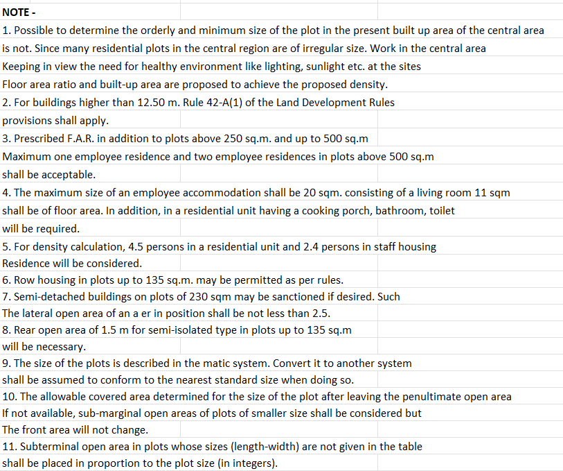
There is no universal submission drawing checklist that can be applied identically to every residential project.
The required drawings and information can depend on the local authority, site conditions, building type, plot characteristics, and applicable development regulations.
For this reason, the information in this article should be treated as a general educational guide.
Before preparing drawings for an actual approval application, verify the current requirements with the concerned authority and have the drawings prepared or reviewed by the appropriate qualified professional.
For general reference, you can also refer to the National Building Code of India (NBC 2016) published by the Bureau of Indian Standards.
Frequently Asked Questions
What is included in a residential submission drawing set?
A residential submission set may include a site plan, floor plans, elevations, sections, area calculations, and other drawings or documents required by the relevant authority.
Is a floor plan enough for building submission?
Usually, a complete submission package involves more than a floor plan. The required documents depend on the project and local authority.
What is the difference between a site plan and a floor plan?
A site plan shows the proposed building in relation to the entire plot, road, open spaces, and other site information. A floor plan mainly explains the arrangement of spaces within a particular floor.
Why is a section drawing required?
A section helps communicate vertical information such as floor levels, heights, plinth, staircase arrangement, roof level, and other vertical relationships.
Does every residential building need the same submission drawings?
No. Requirements can vary according to location, authority, project type, building size, and other conditions.
Can a submission drawing be used as a working drawing?
Not automatically. Working drawings generally contain more detailed information required for construction execution.
Why should the site plan and floor plan be coordinated?
Both drawings represent the same proposed building. If their building footprints, dimensions, access points, or other information conflict, the drawing set may become confusing or inaccurate.
What scale should be used for a submission drawing?
The appropriate scale depends on the drawing, sheet size, project, and authority requirements. Always follow the applicable submission standard rather than assuming one scale is suitable for every project.
Who prepares residential submission drawings?
Submission drawings are generally prepared by an appropriately qualified architect, engineer, or other professional authorized according to the applicable local rules.
Can an online submission drawing be copied for another property?
An existing drawing should not be copied directly for another site. Every project has its own plot dimensions, regulations, access conditions, requirements, and design constraints.
Final Thoughts
A residential building submission drawing should be viewed as a coordinated information package rather than simply a collection of architectural pictures.
The site plan explains the relationship between the building and the plot. Floor plans describe the arrangement of spaces. Elevations communicate the external form, while sections explain vertical relationships. Area information and supporting documents add further information required for evaluating the proposal.
The most important quality of a submission set is consistency.
A change in the floor plan may affect the elevation, section, site plan, and area calculations. Reviewing these relationships before finalizing the drawings can make the complete set clearer and more reliable.
If you are learning architectural drafting, studying submission drawings, or preparing a residential project, understanding how these drawings connect is just as important as learning how to draw each individual sheet.
For an actual building project, always verify the current requirements of the concerned authority and obtain professional review before submission or construction.