
How to Read a House Plan on Site: Practical Guide with Dimensions
A house plan may look simple when you first open a drawing, but understanding it correctly on an actual construction site takes more than knowing the names of rooms. You need to understand dimensions, wall positions, door openings, window locations, and the relationship between the drawing and the physical layout.
A small misunderstanding on paper can lead to a misplaced wall, an incorrectly positioned opening, or a room that does not match the intended size. These problems can become expensive to correct once construction progresses.
This guide explains how to read a house plan on site using practical examples, common drawing symbols, and dimension-checking methods. Whether you are a civil engineering student, a site supervisor, a junior architect, or a homeowner following construction work, these steps will help you understand the drawing more confidently.
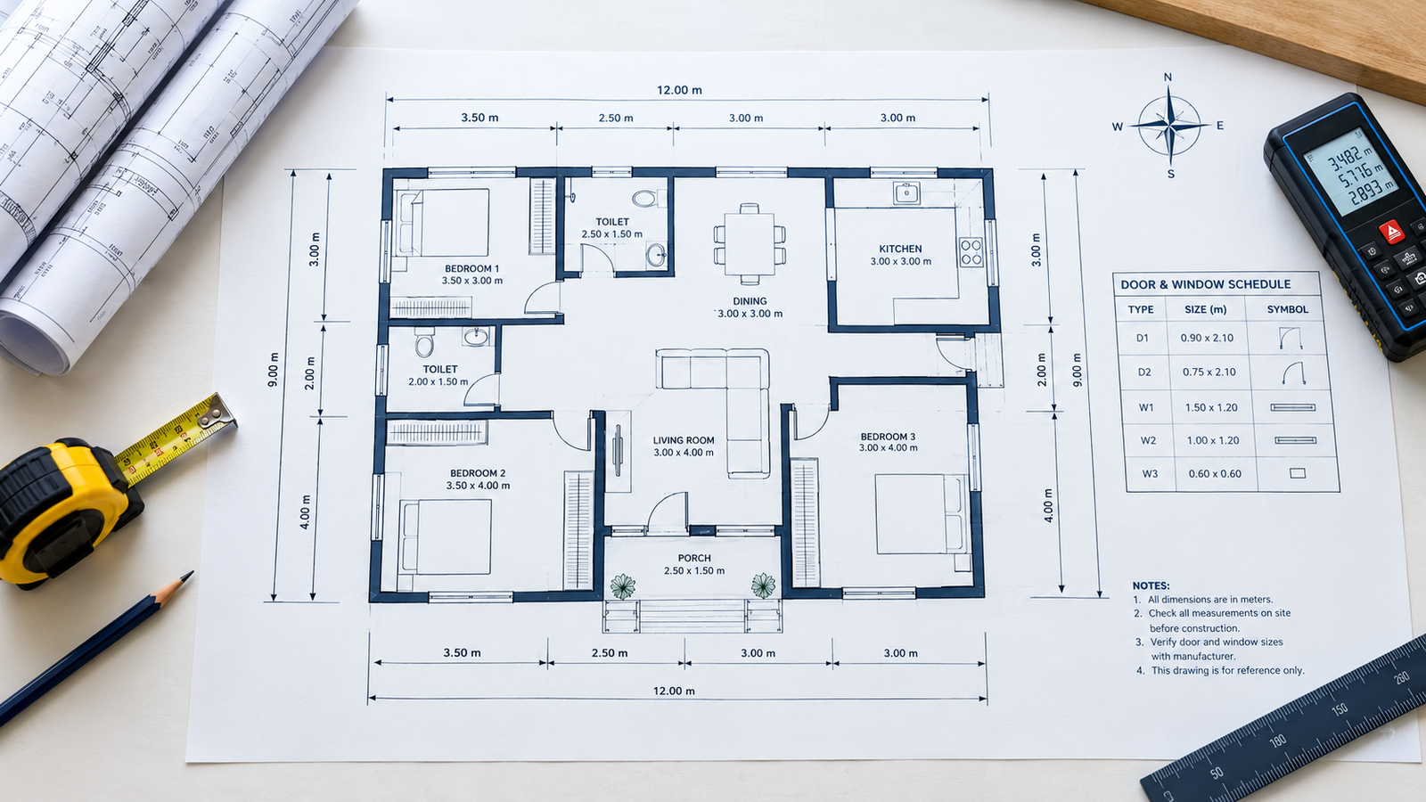
1. Understand What a House Plan Shows
A house plan is generally a horizontal view of a building, as if the structure has been cut at a particular height and viewed from above. It shows the arrangement of rooms, walls, doors, windows, circulation spaces, and other important building elements.
Before taking any measurements, check the drawing title and drawing number. Confirm that you are using the correct floor plan, such as the ground floor, first floor, or terrace plan.
A typical residential floor plan may include:
Room names and internal dimensions.
Wall thicknesses and wall locations.
Door and window positions.
Staircase direction and landing arrangement.
Column locations, where indicated.
Grid lines and structural references, if provided.
Dimension lines showing overall and individual measurements.
Section marks, elevation references, and drawing notes.
Practical site tip: Do not assume that every drawing contains all the information needed for construction. A floor plan may show room layouts, while structural drawings, sections, elevations, and detailed drawings provide additional information.
To understand staircase layouts, step arrangements, and drawing details more clearly, read our guide on Staircase Design Plan.
2. Read the Drawing Scale and Units First
Before interpreting any dimension, check the drawing scale and units.
Architectural plans are often prepared at scales such as 1:50, 1:100, or 1:200. At a scale of 1:100, one unit on the drawing represents 100 of the same units in actual size. For example, 1 cm on a correctly printed 1:100 drawing represents 1 metre in reality.
However, drawings viewed on a computer or mobile screen may be resized. Printed drawings may also have been reduced during copying.
For this reason, always use written dimensions instead of measuring distances directly from the screen or paper whenever dimensions are provided.
In India, residential drawings commonly use millimetres, metres, or feet and inches, depending on the project and drawing standard.
For example:
3000 mm = 3 metres.
4500 mm = 4.5 metres.
10 feet = 3048 mm.
12 feet = 3657.6 mm.
Never mix units without converting them first. If a dimension is written as 3000, check whether the drawing notes specify millimetres before interpreting it as 3000 mm.
3. Understand Dimension Lines Before Measuring
Dimension lines tell you the intended size or distance between building elements. They are usually drawn outside or inside the floor plan, with extension lines pointing towards the relevant faces, edges, or reference points.
A residential plan may contain three important types of dimension
Overall dimensions
These indicate the total length or width of a building or a particular section of it.
For example, the overall external width of a house might be 9000 mm.
Intermediate dimensions
These divide an overall measurement into smaller sections, such as room widths, wall segments, or distances between grid lines.
For example, a 9000 mm building width may be divided into three sections of 3000 mm each, provided that the drawing actually specifies those measurements.
Opening and internal dimensions
These indicate room sizes, door openings, window widths, or other local measurements.
For example, a bedroom may be labelled 3000 × 3600 mm, while its door opening is shown separately.
Do not automatically add every dimension shown on the plan. Some dimensions refer to wall faces, some to centre lines, and others to finished surfaces. Read the dimension endpoints and drawing notes carefully.
4. How to Read a House Plan on the Actual Site
Once you understand the basic drawing information, compare the plan with the physical site in a systematic order.
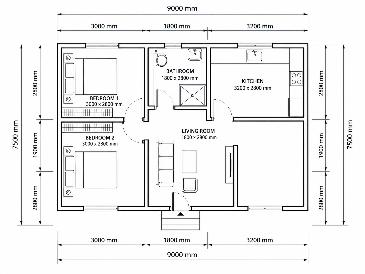
Step 1: Identify the building orientation
Look for the north arrow, plot boundaries, road location, and entrance position. These references help you understand how the building is arranged on the plot.
Do not assume that the top of the drawing always represents north. Follow the north arrow shown on the actual drawing.
Step 2: Locate the main reference points
Identify the approved setting-out references, building grid lines, survey control points, or other fixed references specified for the project.
These points help the site team establish where the building should sit within the plot.
Avoid starting measurements from an arbitrary wall or temporary object. If the starting reference is incorrect, the error may affect several other measurements.
Step 3: Check the overall building dimensions
Read the overall length and width shown on the plan. Compare them with the approved setting-out information and the dimensions marked on site.
For example, if the drawing specifies an overall building width of 9000 mm, verify the relevant reference points using a suitable measuring instrument.
Before accepting the measurement, confirm whether the 9000 mm dimension is measured between external wall faces, grid lines, or another specified reference.
For a better understanding of dimension lines and measurement annotations, you can explore Autodesk’s Dimensioning in AutoCAD tutorial.
Step 4: Identify each room
Follow the room labels and locate the living room, bedrooms, kitchen, toilets, staircase, and other spaces.
Check the dimensions written inside or beside each room. Then confirm which walls define those dimensions.
A room marked 3000 × 3600 mm should not automatically be interpreted as having the same external wall-to-wall measurements. The stated dimensions may refer to clear internal space, structural faces, or finished surfaces, depending on the drawing.
Step 5: Locate walls and openings
Follow the wall outlines to understand the room arrangement. Identify doors, windows, and other openings using their symbols and tags.
Check the position and width of each opening against the written dimensions or door and window schedule.
For example, a door shown near a corner should not be moved simply because another position appears more convenient. Its location may affect furniture placement, circulation, or the adjoining room.
Step 6: Compare the plan with other drawings
Check the architectural floor plan against the relevant structural drawings, sections, elevations, and service drawings.
Look for differences in wall positions, columns, staircase details, floor levels, and openings.
If two drawings appear inconsistent, stop and obtain clarification from the responsible architect or engineer before carrying out affected work.
5. Practical Example: Checking Room Dimensions on Site
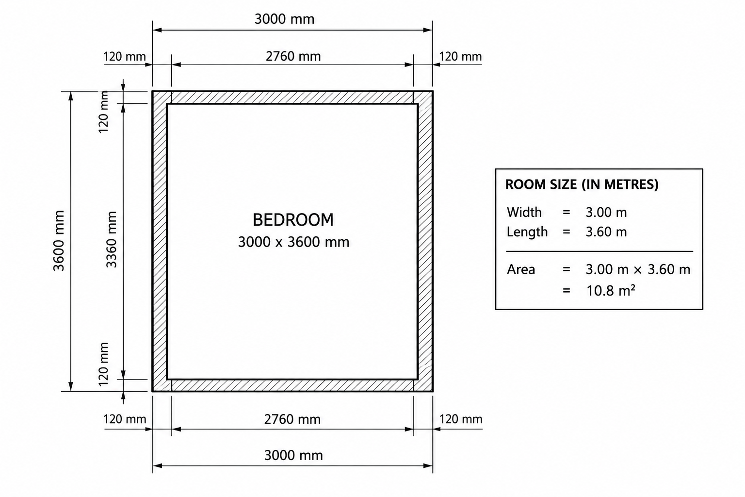
Suppose a residential floor plan shows a bedroom with dimensions of 3000 mm × 3600 mm.
These figures are useful for understanding the intended room size, but first you must confirm how the dimensions are defined.
<text weight=”medium” size=”md”>Example dimension check</text>
The nominal area is calculated as:
Area = Width × Length
Area = 3.0 × 3.6 = 10.8 m²
This calculation assumes a rectangular space with the stated dimensions. It does not establish the actual usable floor area unless the dimension references are known.
How to check it on site
Locate the two walls that define the bedroom width.
Confirm whether the drawing dimension refers to internal faces, finished faces, or another reference.
Measure between the corresponding points using a suitable tape or laser measuring device.
Repeat the process for the room length.
Record the measurements and compare them with the drawing.
Investigate any difference before the work is covered by plaster, flooring, or other finishes.
If the room measures differently from the plan, do not immediately shift a wall. Check the dimension reference, wall thickness, setting-out marks, and drawing revision first.
6. Understand Wall Thickness and Centre Lines
Wall thickness is one of the most common sources of confusion when reading residential drawings.
A plan may show a wall as two parallel lines. The distance between those lines represents the wall thickness graphically, but the written dimensions determine how that wall should be set out.
Consider a simplified example:
Internal clear room width: 3000 mm.
Wall thickness on one side: 115 mm.
Wall thickness on the opposite side: 115 mm.
If these dimensions describe a simple rectangular room with the clear width measured between the internal wall faces, the corresponding external width would be:
3000 + 115 + 115 = 3230 mm.
This is only an illustrative calculation. Actual wall thicknesses and measurement references must come from the project drawings.
What is a centre line?
A centre line passes through the middle of a wall, column, or other element. Centre-line dimensions are often used for structural setting-out and construction calculations.
Do not confuse a centre-line dimension with a clear internal dimension. They describe different measurement references.
On site, identify the intended reference before marking wall positions. Where structural grids are provided, use the approved grid and setting-out details rather than estimating wall positions from room labels.
7. How to Read Door and Window Positions
Doors and windows influence room access, natural light, ventilation, furniture placement, and circulation. Their positions should therefore be checked carefully.
A floor plan commonly shows door leaves, opening directions, and window symbols. Specific door or window tags may refer to a schedule containing the required sizes and details.
When checking an opening, confirm:
The opening width and height from the relevant drawing or schedule.
Its location relative to the specified wall face, corner, or grid.
The door swing direction, where applicable.
The window position and sill level, where specified.
Any lintel, beam, or structural requirement affecting the opening.
Coordination with electrical points, plumbing fixtures, and built-in furniture.
For example, if a bedroom door is shown 300 mm from a particular wall face, first check how that 300 mm is dimensioned. It may refer to the edge of the opening, the frame, or another reference point.
Never estimate the opening position by eye when the drawing provides a dimension.
8. How to Read a Staircase on a House Plan
Staircases can be difficult to interpret because a floor plan only shows part of their three-dimensional arrangement.
Look for the stair direction arrow, tread layout, landing, stair width, and any indication of the direction of travel. Check the ground-floor and upper-floor plans together.
Important details include:
The location and width of the staircase.
The number and arrangement of steps.
The landing dimensions.
The direction of ascent or descent.
The floor-to-floor height.
The headroom and vertical clearance.
The relationship between the staircase and nearby doors or walls.
The floor-to-floor height and staircase section should be checked together to confirm riser and tread details. Do not determine the number of steps from the floor plan alone if the relevant section or staircase detail is available.
For practical staircase drawing guidance, refer to the separate staircase plan and section drawings supplied for the project.
9. Check Levels, Sections, and Elevations
A floor plan mainly explains horizontal arrangement. It does not show every vertical relationship within a building.
Levels, sections, and elevations provide additional information about floor heights, lintels, window sills, roof levels, parapets, and other vertical details.
Before construction proceeds, check the applicable drawings for:
Plinth level and finished floor level.
Floor-to-floor height.
Door and window sill levels.
Lintel and beam levels.
Staircase headroom.
Roof slope or terrace level, where applicable.
Ground levels and drainage falls, where specified.
A room can match its plan dimensions and still have a problem if its floor level or opening height is incorrect.
When a level is unclear or inconsistent between drawings, request clarification instead of assuming that all floors or openings have identical levels.
For information on building requirements and construction standards in India, refer to the National Building Code of India published by the Bureau of Indian Standards (BIS).
10. Common Mistakes When Reading a House Plan on Site
Measuring from the wrong reference point
A measurement taken from a finished wall face may not match a dimension intended for a centre line or structural face.
Better approach: Identify the exact endpoints of each dimension before measuring.
Using the drawing scale instead of written dimensions
A resized print or screen view can give misleading measurements.
Better approach: Use written dimensions and verify the drawing scale only when necessary.
Ignoring wall thickness
The clear room size and the overall wall-to-wall size are not always the same.
Better approach: Read internal and external dimensions separately.
Following an outdated drawing
A previous revision may show a wall, door, or staircase position that has since changed.
Better approach: Confirm the latest approved drawing revision before setting out.
Checking the architectural plan alone
A room layout may appear correct even when it conflicts with a beam, column, pipe route, or electrical installation.
Better approach: Coordinate architectural, structural, and service drawings before executing affected work.
Making adjustments without approval
Moving a wall or opening to suit site conditions may affect structure, services, or compliance requirements.
Better approach: Record the discrepancy and obtain approval from the responsible professional before changing the layout.
Before construction drawings are used on site, it is important to identify and resolve common drawing errors. Read our guide to Common Mistakes in Submission Drawings for additional drawing-checking tips.
11. A Simple House Plan Checking Checklist for Site Work
Use this checklist before setting out walls or checking room layouts.
Confirm the drawing title, floor, number, and latest revision.
Check the drawing units and relevant notes.
Identify the north arrow and plot orientation.
Locate approved survey and setting-out reference points.
Verify the overall building dimensions.
Check room dimensions and their measurement references.
Confirm wall positions and thicknesses.
Verify door and window locations.
Check column and grid locations against structural drawings.
Review staircase dimensions and sections.
Confirm floor levels and relevant vertical dimensions.
Coordinate plumbing, electrical, and other service requirements.
Record discrepancies and obtain clarification before proceeding.
The checklist should be adapted to the project and used alongside the applicable construction documents.
12. What to Do When Site Measurements Do Not Match the Plan
Differences between drawing dimensions and site measurements should be investigated before construction continues in the affected area.
Start by repeating the measurement and confirming that the correct reference points were used. Check whether the drawing dimension refers to a centre line, structural face, internal face, or finished surface.
Next, verify the drawing revision and compare the architectural plan with relevant structural and detailed drawings. Record the measured dimensions and mark the location of the discrepancy clearly.
If the difference remains unresolved, inform the responsible architect, engineer, or site coordinator and request written clarification or a revised drawing where required.
Do not alter structural elements, shift columns, reduce required clearances, or relocate openings based on an assumption. Any proposed change must be reviewed and approved by the appropriate professional.
Conclusion
Reading a house plan on site becomes much easier when you follow a consistent process: confirm the drawing revision, understand the dimension references, locate the setting-out points, check room sizes, and coordinate the plan with sections, elevations, and structural drawings.
The most important skill is not simply reading a number from a drawing. It is understanding exactly what that number measures and how it relates to the building being constructed.
By checking dimensions carefully and resolving discrepancies before work progresses, site teams can reduce avoidable mistakes and improve coordination between drawings and actual construction.
Always follow the latest approved project drawings, applicable local building requirements, and instructions from the responsible design and engineering professionals.