
Layer Management for Architectural Drawings: Workflow, Plotting and Quality Control
Introduction
AutoCAD layer standards help architects, draftsmen, and CAD professionals maintain clear, organized, and editable drawings. When a project contains architectural plans, elevations, sections, dimensions, annotations, and service layouts, inconsistent layer management can make even a simple drawing difficult to understand.
A well-structured layer system gives every drawing element a clear purpose. It also makes editing easier, improves coordination between team members, and reduces mistakes when drawings are revised or shared with clients.
Instead of creating layers randomly during drafting, it is better to establish a consistent system before starting a project. This guide explains how to create meaningful layer names, organize drawing files, assign properties, and check layer quality before delivering an AutoCAD drawing.
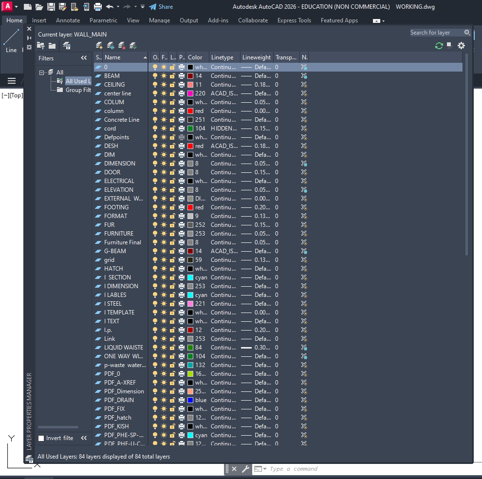
1. Why AutoCAD Layer Standards Matte
Layer standards are not just about keeping the Layer Properties Manager tidy. They influence how efficiently a drawing can be edited, reviewed, printed, and reused.
Improve drawing readability: Separate walls, doors, windows, dimensions, furniture, and annotations so that each category can be managed independently.
Reduce editing time: Layers allow users to hide, freeze, lock, or modify related objects without selecting them individually.
Maintain consistency: A shared naming and property system helps different team members produce drawings with a similar appearance.
Simplify plotting: Proper layer colors, lineweights, and plot settings help produce readable PDF sheets and printed drawings.
Support project revisions: Clearly named layers make it easier to identify which drawing elements need updates.
Improve coordination: Organized layers make architectural drawings easier to review alongside structural and building-services information.
The main objective is to make every layer understandable to another CAD user who did not create the original drawing.
If you are new to CAD drafting, read our AutoCAD Basics for Beginners guide to understand essential commands, drawing tools, and the basic AutoCAD workflow.
2. AutoCAD Layer Naming Rules for Professional Drawings
A layer name should communicate what the objects represent and how they are used. Names such as Layer1, New Layer, or Miscellaneous do not provide enough information for reliable project coordination.
Follow these naming practices:
Use descriptive names: Choose names such as A-WALL, A-DOOR, A-WINDOW, A-DIMS, and A-TEXT for architectural drawing categories.
Adopt a consistent prefix system: Use prefixes such as A- for architectural, S- for structural, and M- for mechanical elements when they suit the project’s requirements.
Separate object categories: Keep walls, doors, windows, furniture, dimensions, and room labels on suitable layers instead of combining unrelated objects.
Keep names short and readable: Avoid long sentences or unnecessary abbreviations that make layer lists difficult to scan.
Use one naming style: Decide whether the project uses uppercase names, hyphens, or another separator, and apply the rule consistently.
Avoid duplicate meanings: Do not create several layers with slightly different names for the same purpose.
Define special-purpose layers carefully: Temporary construction guides, revision marks, and non-printing reference geometry should have clear, documented names.
Follow client standards where required: If a client, consultant, or organization supplies a CAD standard, use that naming convention rather than introducing an incompatible system.
These examples are starting points, not universal naming requirements. The correct layer structure depends on the project, discipline, and delivery specifications.
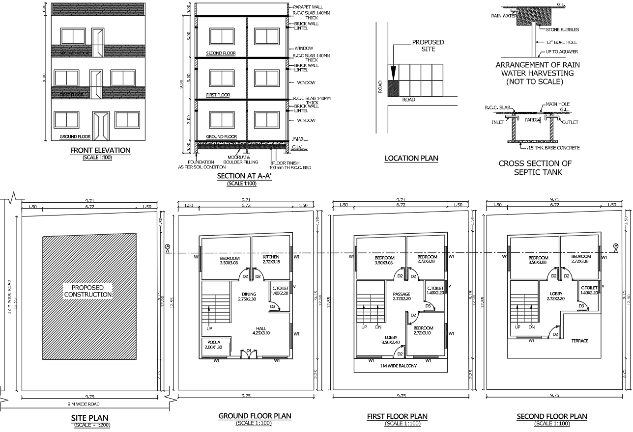
3. Recommended Layer Categories for Architectural Drawings
Architectural drawings often contain many different types of information. Grouping these elements by function makes the file easier to control.
Wall layers: Use dedicated layers for wall outlines, internal partitions, and other wall-related geometry where separate control is useful.
Door and window layers: Keep door swings, frames, window outlines, and related symbols organized for easier editing.
Dimension layers: Place linear dimensions, levels, and other measurement annotations on clearly identified layers.
Text and annotation layers: Separate room names, notes, labels, and general drawing annotations from physical building geometry.
Furniture and fixture layers: Use distinct layers for furniture layouts, sanitary fixtures, and other interior elements when they need independent visibility.
Hatch layers: Keep material patterns and area fills separate from the geometry they represent.
Centerline and hidden-line layers: Manage centerlines and hidden details independently when the drawing requires these line types.
Reference and construction layers: Place temporary guides or external reference information on clearly named layers with suitable visibility and plotting settings.
Revision layers: If revisions are highlighted on separate layers, define how they will be reviewed, plotted, and removed or archived after approval.
Avoid creating a separate layer for every individual object unless the project genuinely requires that level of control. Too many unnecessary layers can make management more complicated.
4. How to Set Layer Colors, Linetypes and Lineweights
Layer names identify drawing categories, while layer properties control how those categories appear and print. A consistent property system helps users distinguish important geometry from supporting information.
Assign colors with a purpose: Use an agreed color scheme that helps users identify drawing categories quickly. Do not rely on color alone to communicate the meaning of an object.
Choose appropriate lineweights: Major outlines may require stronger visual emphasis than dimensions, hatches, or secondary details.
Use linetypes consistently: Apply continuous, dashed, or center linetypes where the drawing conventions require them.
Configure plot behavior: Check whether each layer should print, remain non-printing, or use a specific plot style.
Use ByLayer properties where practical: Setting object colors, linetypes, and lineweights to ByLayer makes the drawing easier to maintain through layer-level changes.
Check linetype scale: Dashed lines and centerlines should display clearly at the intended drawing scale and on the final plotted sheet.
Review grayscale output: If drawings will be printed in black and white, verify that lineweight and linetype differences remain readable.
Do not assume that a particular color always represents the same lineweight in every office. Plot styles, CTB/STB settings, and project requirements can change how layer properties are printed.
For more information about managing layer colors, linetypes, lineweights, and visibility, refer to the official AutoCAD Layer Properties Manager guide.
5. AutoCAD File Organization for Reliable Project Work
Layer standards are more effective when the drawing files themselves follow a consistent structure. Good file organization reduces confusion when several drawings are developed or revised together.
Use meaningful file names: Include a project identifier, drawing type, level, or drawing number according to the project’s naming convention.
Separate drawings by purpose: Keep floor plans, elevations, sections, details, and service drawings in clearly organized files or folders when appropriate.
Maintain a standard folder structure: Separate working drawings, external references, issued PDFs, blocks, and archived revisions where the project workflow benefits from it.
Manage external references carefully: Use relative paths when suitable for portable project folders, and verify that referenced files remain accessible before sharing the drawing.
Use consistent block libraries: Store reusable doors, windows, symbols, and title blocks in approved locations rather than creating unnecessary variations.
Keep issued files separate from active work: Distinguish current working drawings from approved or previously issued deliverables.
Apply a revision naming system: Record revision identifiers and issue dates according to the project procedure without relying on vague names such as final-new or final-latest.
Clean up unnecessary content: Remove obsolete temporary objects and unused definitions when appropriate, while preserving information required by the project.
A clean folder structure and a clear layer system solve different problems, but both are needed for dependable CAD handovers.
6. Using Layer States and Visibility Controls

Layer visibility tools help users review complex drawings without permanently changing the underlying geometry.
Freeze unnecessary layers: Hide categories that are not needed for the current task, especially in large or detailed drawings.
Lock completed layers: Protect finished geometry from accidental changes while allowing other parts of the drawing to be edited.
Use layer states: Save useful visibility and property configurations for different review or drafting tasks.
Review viewport-specific visibility: In layouts, check viewport layer overrides where different sheets need different information displayed.
Handle reference layers consistently: Decide how external references and background information should appear in working drawings and plotted sheets.
Restore the intended layer configuration: Before saving or issuing a drawing, confirm that the correct layers are visible, thawed, and configured for the intended output.
Visibility settings should support the drawing workflow without hiding information that reviewers or recipients expect to see.
You can also explore Autodesk’s guide to controlling AutoCAD layers for additional information about layer visibility, locking, and viewport-specific properties.
7. Common AutoCAD Layer Management Mistakes
Layer problems often develop gradually as drawings are edited by multiple people. Identifying them early helps prevent unnecessary rework.
Using default layer names: Generic names make it difficult to understand a drawing without examining individual objects.
Mixing unrelated objects: Placing dimensions, wall geometry, furniture, and notes on one layer limits visibility control.
Creating duplicate layers: Slight spelling differences and inconsistent abbreviations can create unnecessary layers with overlapping purposes.
Ignoring object properties: Objects with manually assigned colors or lineweights may not respond as expected to layer changes.
Using inconsistent naming conventions: Different prefixes or abbreviations across drawings make project coordination less predictable.
Leaving temporary geometry behind: Construction lines and obsolete revision marks can appear in issued drawings if they are not reviewed.
Forgetting plot settings: A drawing can look correct on screen but produce faint, heavy, or missing lines when exported.
Overcomplicating the layer list: Excessive layers with no clear function increase maintenance effort and make the drawing harder to navigate.
Correcting these issues during drafting is generally easier than repairing them immediately before a deadline.
8. AutoCAD Layer Quality Checks Before Drawing Submission
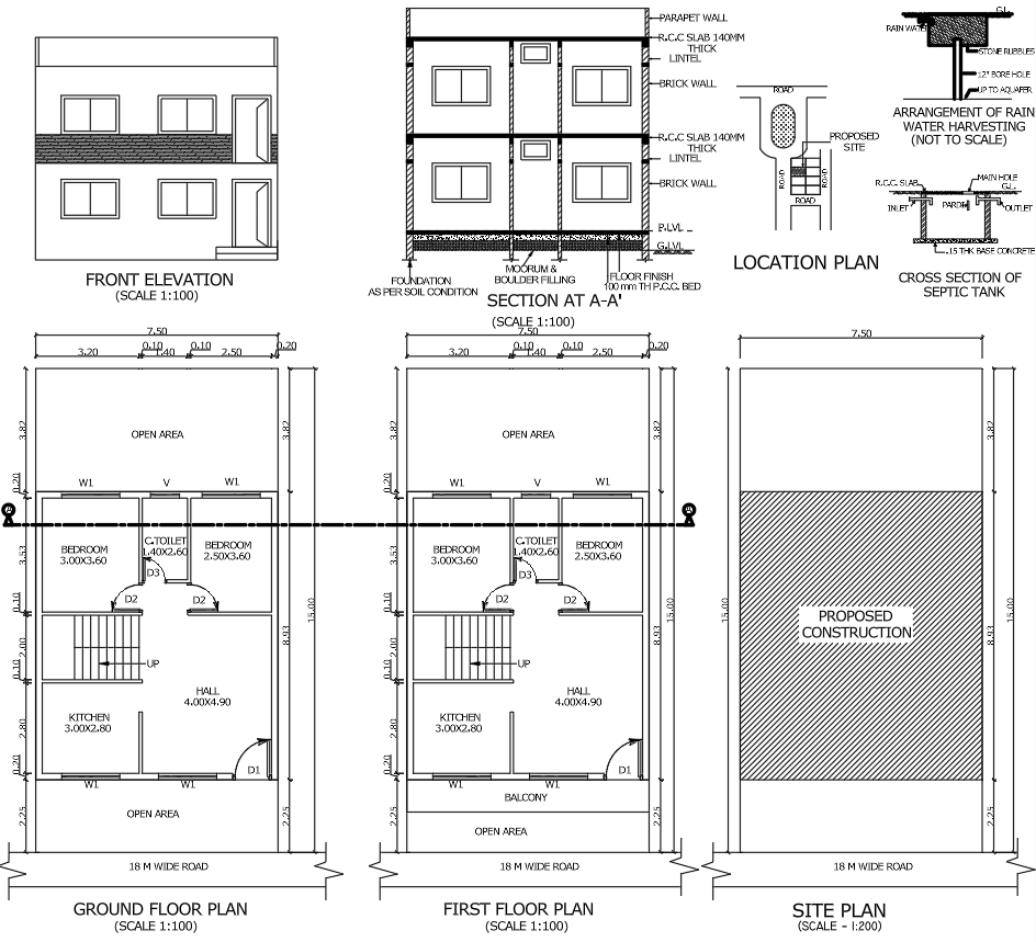
Before sharing a DWG file or issuing a PDF, perform a structured quality review rather than relying only on a visual inspection.
Check layer names: Confirm that names follow the agreed project convention and that no unexplained duplicates remain.
Review object assignments: Verify that walls, doors, dimensions, annotations, hatches, and other elements are assigned to suitable layers.
Inspect object properties: Look for manually overridden colors, linetypes, and lineweights where ByLayer settings are expected.
Check layer visibility: Make sure required information is not accidentally hidden or frozen.
Verify non-printing layers: Confirm that construction guides and other reference-only elements do not appear in the final plotted output.
Review external references: Check for missing files, broken paths, and outdated references that may affect the drawing.
Inspect layouts and viewports: Confirm that sheet viewports show the intended information and that any layer overrides are deliberate.
Preview the final PDF: Check lineweights, text readability, dimensions, hatches, sheet orientation, and page scaling.
Remove obsolete drawing content: Delete unnecessary temporary geometry when safe, and review unused blocks or layer definitions before cleaning the file.
Check drawing integrity: Use appropriate AutoCAD tools, such as AUDIT, when necessary to identify and address drawing database errors.
Save a clean deliverable: Verify the drawing name, revision, file location, and required supporting files before issuing the package.
These checks help detect both layer-related errors and broader file-delivery problems that can affect drawing quality.
For a complete drawing preparation workflow, explore our guide on how to create submission drawings in AutoCAD, including layer setup, dimensioning, and plotting.
9. Creating a Reusable AutoCAD Layer Standard
For teams handling repeated projects, a reusable standard is more reliable than rebuilding the layer system for every drawing.
Create a standard template: Set up approved layers, common properties, text styles, dimension styles, and layouts in a suitable DWT template.
Document naming rules: Provide a short guide explaining prefixes, abbreviations, layer purposes, and plotting behavior.
Define responsibility: Decide who can create new layers and how changes to the standard should be approved.
Test the template: Create a sample drawing, check the plotted output, and confirm that the template supports normal project tasks.
Review the standard periodically: Update it when project requirements, office workflows, or client specifications change.
Train team members: Make sure everyone understands how to use the template and why consistent layer management matters.
A practical standard should be detailed enough to prevent confusion but simple enough that drafters can follow it during everyday work.
Conclusion
AutoCAD layer standards provide a practical foundation for organized architectural drafting. Consistent naming rules, sensible layer categories, controlled object properties, and structured file storage make drawings easier to edit and review.
The most reliable approach is to define the layer system before drafting, apply it consistently throughout the project, and verify both the DWG file and plotted sheets before submission. By turning these practices into a repeatable workflow, CAD professionals can reduce avoidable errors and create drawings that are easier for other team members and clients to understand.