
Building Elevation Drawings for Approval: Design, Dimensions and Review Guide
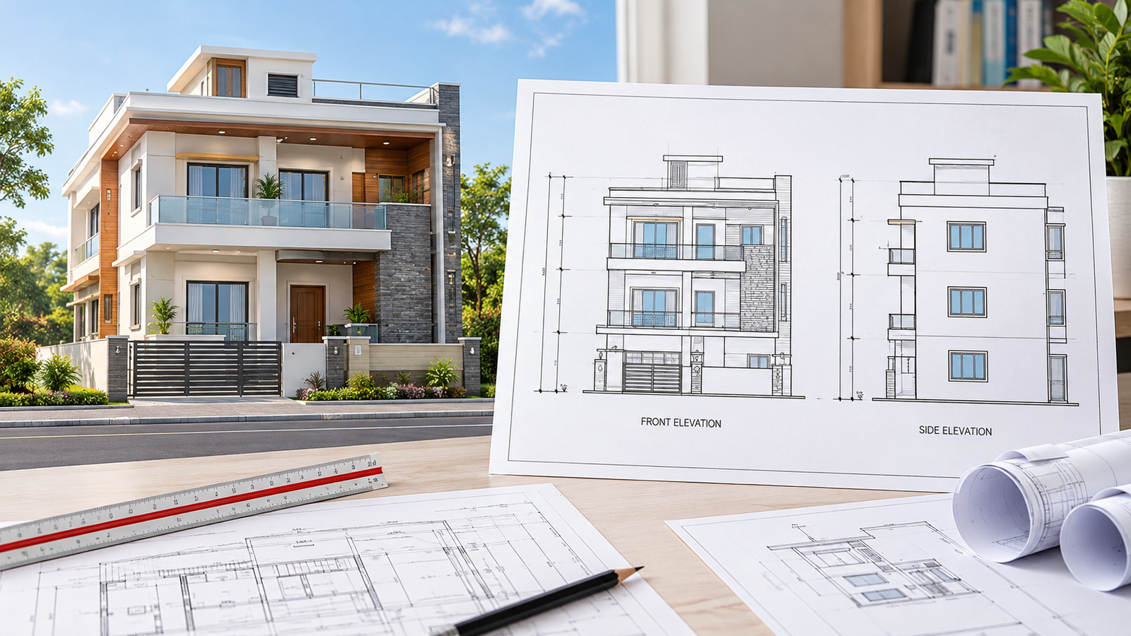
A building elevation drawing explains how a proposed building will appear when viewed from the outside. It translates the architectural design into a measurable vertical view, helping reviewers understand the building’s facade, floor arrangement, openings, roof outline and relationship with the ground.
For a building approval application, an elevation should communicate more than the appearance of the front wall. Its dimensions and visible features must correspond with the proposed floor plans and building sections. If a balcony, window, staircase enclosure or roof projection is shown differently across the drawings, the design may require clarification before the application can be processed.
This guide focuses on the preparation and technical review of building elevations for approval. It explains how to develop clear facade views, coordinate architectural features, check vertical proportions and prepare drawings that are easier to interpret.
Important: Drawing formats and approval requirements vary by municipal authority, development authority, location and building type. Always verify the current local submission guidelines before finalising your drawings.
What Makes an Elevation Drawing Suitable for Building Approval?
An approval-oriented elevation should allow the reviewer to understand the external configuration of the proposed building without making assumptions about its dimensions or arrangement.
A useful elevation drawing communicates the following information:
Building profile: The overall outline, including the roof, parapet, balconies and other visible projections.
Vertical arrangement: The relationship between ground, plinth, floor and roof levels.
External openings: The position and approximate proportions of doors, windows and ventilators.
Architectural features: Recessed walls, shading elements, entrance canopies and other significant facade components.
Ground relationship: The connection between the building base and the relevant ground or site level.
Drawing identification: A clear view title, drawing scale, dimensions and project references as required.
The amount of detail should match the purpose of the submission. Decorative information that does not help explain the approved design should not overpower the essential dimensions and building outline.
1. Select the Elevation Views Required for the Project
The number and orientation of elevation views depend on the building design and the applicable authority’s requirements.
Front Elevation
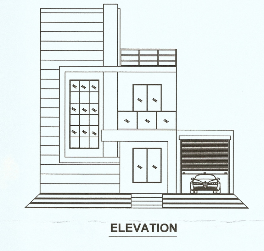
The front elevation represents the building face generally viewed from the principal approach or frontage. It helps explain the entrance arrangement, facade composition, floor divisions and visible projections.
Check that:
The main entrance is positioned consistently with the floor plan.
Windows and doors correspond to the correct rooms.
Balcony edges and entrance canopies are shown in their intended positions.
Floor divisions and roof outlines reflect the proposed design.
The building’s principal height information is clearly identified where required.
Rear Elevation
A rear elevation explains the exterior face that may not be visible from the main approach. It can reveal service openings, rear balconies, kitchen windows, utility spaces and changes in the rear wall profile.
Prepare this view when required by the submission guidelines or when it is necessary to explain the building’s external configuration.
Side Elevations
Side elevations are useful for understanding the building’s depth, side openings, stairwell windows and external projections. They are particularly important when the two sides have different arrangements or when the site has a sloping ground profile.
Do not assume that a side elevation is unnecessary simply because the building has a symmetrical front facade. Confirm which views are required for the specific application.
The required elevation views, sections and drawing details may vary according to the approving authority. You can refer to the building permission procedure published by Goa’s Town and Country Planning Department for an example of how drawings are specified in an official submission process.
2. Establish Accurate Floor and Height Relationships
Vertical dimensions are among the most important technical elements of an approval elevation. They help communicate the proposed building’s height and the relationship between its different levels.
Depending on the project and applicable regulations, the drawing may identify:
Existing or natural ground level, where required.
Proposed ground level.
Plinth level.
Finished floor levels.
Floor-to-floor heights.
Roof or terrace level.
Parapet level.
Overall building height.
Use a consistent level reference across the drawing set. The level values must be based on verified site information and the actual architectural design.
Building height and level information should be checked against the applicable local regulations. For additional guidance on building standards in India, refer to the National Building Code of India published by the Bureau of Indian Standards.
How to Review Vertical Dimensions
Before finalising an elevation:
Compare the floor-to-floor heights with the corresponding building section.
Verify that the plinth level is consistent with the proposed site and floor information.
Check the roof and parapet levels against the architectural design.
Confirm how overall building height must be measured under the applicable local rules.
Recheck the dimensions after any change to the number of floors or roof configuration.
A visually attractive elevation is not sufficient if its stated dimensions contradict the other drawings.
3. Coordinate Windows, Doors and Other Openings
Openings influence both the appearance of a facade and the practical arrangement of the rooms behind it. Their position should therefore be coordinated with the floor plan rather than adjusted only to improve the external design.
For example, moving a bedroom window to create a more balanced facade can affect its relationship with the internal room layout. Similarly, changing a balcony door may require updates to the floor plan and other relevant views.
Review these points:
Window widths and heights match the intended design.
Openings align with the correct rooms and wall locations.
Door positions correspond with the entrance and circulation layout.
Ventilators and service openings are represented where applicable.
Balcony doors and external projections agree with the plan.
Any revisions are reflected across all affected drawings.
Exact opening dimensions should be shown according to the drawing’s purpose and the authority’s requirements. Avoid adding unsupported dimensions simply to make the sheet appear more detailed.
4. Represent the Roof, Parapet and External Projections Clearly
The roofline can significantly affect how the proposed building’s height and silhouette are interpreted. Flat roofs, sloping roofs, parapet walls and staircase enclosures should be represented according to the actual design.
Particular attention may be needed for:
Parapet walls: Show their location and relevant height dimensions where required.
Staircase headroom structures: Confirm that any enclosure above the roof corresponds to the staircase arrangement and section.
Balconies: Represent their depth, position and visible edges consistently with the plan.
Sunshades and canopies: Include projections that are relevant to the proposed facade or required for approval.
Roof projections: Identify significant roof elements that affect the external building profile.
Do not omit a visible structure merely because it is not part of the main occupied floor area. Where it affects the proposed building’s appearance or regulated height, check the applicable submission and measurement requirements.
5. Show Materials and Facade Finishes Without Reducing Clarity
An elevation may communicate the intended external finishes through simple notes, restrained hatching or clearly differentiated surface treatments. The method depends on the required drawing format.
For an approval drawing, the main objective is to make the building configuration understandable. Excessive textures, dark fills or decorative effects can hide openings, dimensions and important outline changes.
Use these drafting practices:
Keep the principal building outline visually distinct.
Use consistent line weights for walls, openings and secondary features.
Label important materials when the submission requires them.
Keep dimensions and text readable at the final printed scale.
Avoid unnecessary decorative elements that obscure technical information.
Use a legend if different line types or symbols need explanation.
Detailed renderings may be useful for presentation, but they should not replace the dimensioned elevation required for technical review.
6. Coordinate the Elevation With the Floor Plan and Section
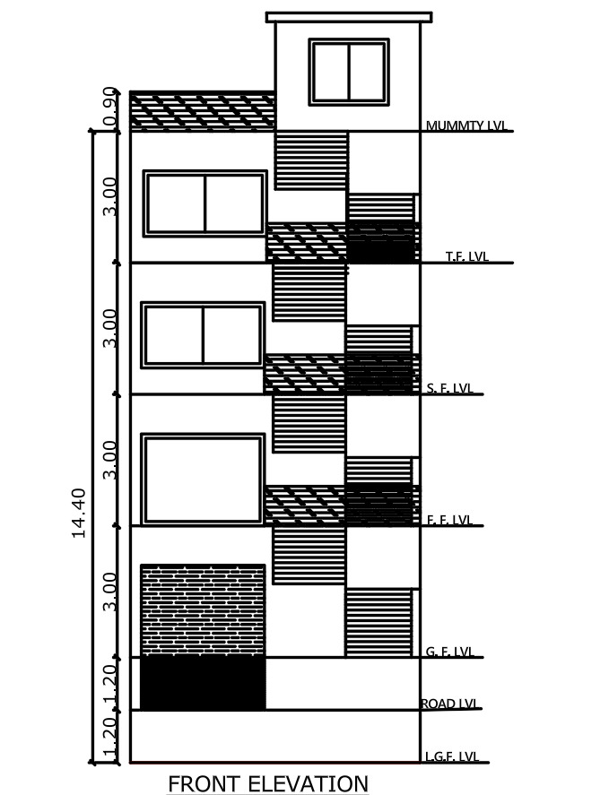
Check Window and Door Positions: Ensure that windows and doors shown in the elevation match their locations and sizes in the floor plan.
Verify Floor Levels: Compare the floor levels and floor-to-floor heights in the elevation with the corresponding building section.
Match Balcony and Projections: Confirm that balconies, sunshades, entrance canopies and other projections are shown consistently in the floor plan and elevation.
Coordinate Roof Details: Check that the parapet walls, staircase headroom and roof outline match the roof plan and building section.
Confirm Plinth and Ground Levels: Ensure that the plinth level and relevant ground references are consistent with the site information and section drawing.
Check Overall Building Height: Verify the building height and roof level against the dimensions and references shown in the section drawing.
Update All Drawings After Revisions: If a window, balcony, floor level or roof detail changes, revise every affected drawing to maintain consistency across the submission set.
Review Before Submission: Compare the floor plan, elevation and section together to identify mismatched dimensions, missing features or conflicting information before finalising the drawings.
For better accuracy, compare floor levels, roof heights and vertical dimensions with the corresponding section drawing for building submission before finalising the elevation.
Practical Coordination Example
Suppose a proposed first-floor balcony is extended during design development. The revision may affect the front elevation, floor plan, roof or projection information and relevant dimensions.
Updating only the elevation can leave the submitted drawing set inconsistent. Record the design change and revise every affected view before issuing the final sheets.
This coordination process is more useful than judging the elevation only by its visual appearance.
7. Choose a Suitable Drawing Scale and Sheet Layout
The drawing scale should make the facade, dimensions and annotations readable while fitting the required information onto the prescribed sheet format.
A suitable scale depends on the size of the building, the complexity of the facade and the authority’s submission standards. Do not assume that one scale is mandatory for every project.
When arranging the sheet:
Give each elevation a clear title and orientation.
Maintain adequate space for dimensions and level markers.
Avoid overlapping text, leaders and extension lines.
Use consistent annotation sizes across related sheets.
Keep the drawing within the required printable area.
Check the exported PDF or printed copy rather than relying only on the CAD workspace.
If a dimension becomes unreadable after plotting, revise the sheet layout or annotation settings before submission.
8. Common Elevation-Specific Problems and Their Solutions
Incorrect Window Alignment
Problem: Windows appear at different positions in the elevation and floor plan.
Solution: Verify the wall and opening locations in the plan, then revise the elevation to reflect the approved design.
Inconsistent Floor Heights
Problem: The floor levels shown on the elevation do not agree with the building section.
Solution: Establish a consistent level reference and recalculate the affected vertical dimensions.
Missing Roof Structures
Problem: A staircase enclosure, parapet or other visible roof element is absent from the elevation.
Solution: Compare the elevation with the roof plan and section, then include relevant features as required.
Unclear Ground Level
Problem: The relationship between the building base and surrounding ground cannot be interpreted easily.
Solution: Show the required ground and plinth references using verified site information.
Excessive Decorative Detailing
Problem: Heavy hatching, textures or presentation effects make the dimensions difficult to read.
Solution: Prioritise technical clarity and retain only the visual information necessary for the intended submission.
Outdated Revisions
Problem: A previously changed balcony, window or roof feature remains in one of the submitted views.
Solution: Check the latest design revision against every affected sheet before exporting the final drawing set.
9. Final Review Before Submitting an Elevation Drawing
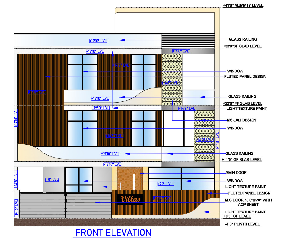
Use this focused review checklist before issuing the elevation sheet:
Required front, rear or side views are included.
Each elevation has a clear title and orientation.
Building outlines match the current architectural design.
Door and window positions correspond with the floor plans.
Floor and roof levels agree with the relevant sections.
Required building height dimensions are clearly stated.
Parapets, balconies and significant projections are represented.
Ground and plinth references are based on verified information.
Dimensions, labels and line weights remain readable after plotting.
The latest revisions are reflected in all affected drawings.
Project identification and professional details meet the prescribed format.
Local submission requirements have been checked.
This checklist is intended as a drafting quality-control aid, not a substitute for the official requirements of the approving authority.
Before sending the final drawings, use a building submission drawing checklist to review the required documents, drawing coordination and essential submission details.
10. Why a Clear Elevation Drawing Helps the Review Process
A well-organised elevation reduces the effort needed to interpret the proposed exterior. Clear dimensions, coordinated openings and consistent levels make it easier to compare the facade with the rest of the drawing package.
It also provides a reliable reference when the design changes during preparation. Instead of correcting isolated visual elements, the designer can identify the affected dimensions and update the related drawings systematically.
However, a clear elevation alone does not guarantee building approval. The application must also satisfy the applicable planning regulations, documentation requirements and other technical conditions relevant to the project.
Conclusion
Building elevation drawings for approval should communicate the proposed facade accurately, with particular attention to openings, floor relationships, roof features and overall building proportions. Their technical value depends on how consistently they represent the design shown in the floor plans, sections and other relevant drawings.
By checking dimensions, coordinating revisions and reviewing the final plotted sheet, architects and drafting professionals can produce elevation drawings that are easier to interpret and less likely to require clarification for avoidable drafting inconsistencies.
Always confirm the drawing format, required views and building-height rules with the relevant local authority before submission.
Frequently Asked Questions
What is the main purpose of a building elevation drawing?
It communicates the external appearance and vertical arrangement of a proposed building, including its openings, roof profile, floor relationships and relevant height information.
Which elevation views are needed for building approval?
The required views depend on the building design and local submission rules. Front, rear and side elevations may be required according to the project and authority guidelines.
Should building height be shown on an elevation?
Where required, the elevation should identify relevant levels and height dimensions. The measurement method must follow the applicable local regulations.
Can a rendered facade image replace an elevation drawing?
A rendered image can help communicate architectural appearance, but it does not necessarily provide the dimensions and technical information required in an approval drawing.
How can elevation drawing errors be reduced?
Compare the elevation with the latest floor plans, sections and roof information. Verify openings, levels, projections and dimensions, then inspect the final plotted sheet for readability and consistency.
Who should prepare or verify an approval elevation?
An appropriately qualified architectural or building-design professional should prepare or review the drawing in accordance with local rules and the project’s requirements.