
Common Submission Drawing Errors: Causes, Fixes and Quality Checks
Introduction
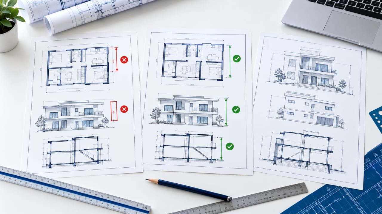
A building submission drawing is a technical document that communicates the proposed design to the concerned building approval authority. Its purpose is not simply to display the layout of a building but to present the design in a clear, coordinated, and verifiable format.
Many drawing-related problems arise when individual sheets are prepared separately without checking how the information connects across the complete project. A floor plan may appear correct on its own, for example, while the corresponding elevation or section shows a different building level or opening position. Such inconsistencies can create questions during the review process and lead to avoidable revisions.
Understanding why these errors occur is more useful than memorizing a list of mistakes. This guide explains practical ways to identify drawing coordination problems, improve technical communication, and review a submission package before it is issued. Specific requirements should always be verified against the applicable local authority’s regulations.
Before preparing the final drawing package, use our building submission drawing checklist to review the essential details that should be checked before submitting plans for approval.
1. Inconsistencies Between Different Drawing Sheets
One of the most important quality issues is a mismatch between related drawings. Each sheet may contain useful information, but the complete set becomes difficult to interpret when the information does not agree.
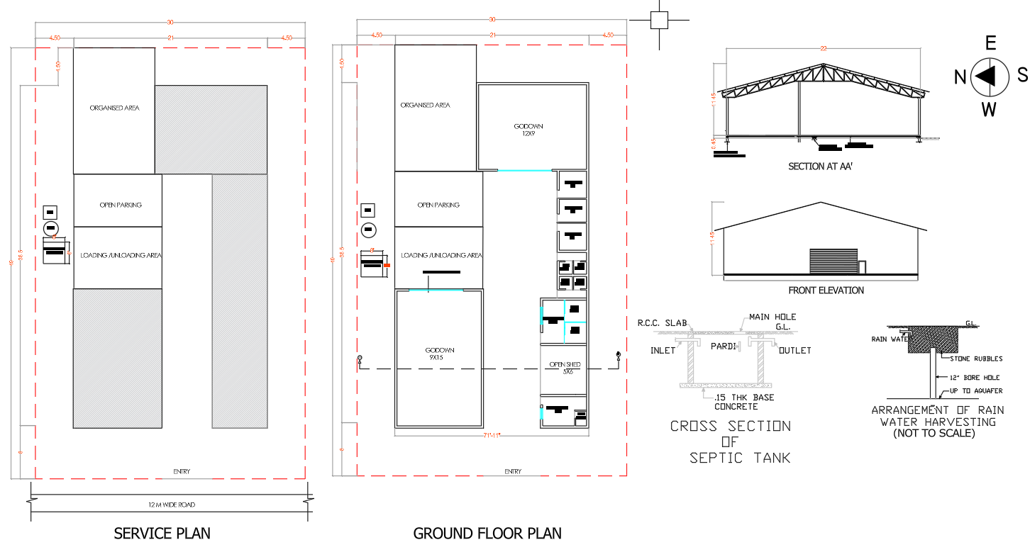
Common causes:
A room layout is revised without updating the corresponding elevation.
Door or window positions differ between the floor plan and elevation.
Staircase geometry is changed without revising the section.
Different drawing sheets are prepared from outdated versions of the design.
How to correct the issue:
Use one approved design layout as the reference for all related sheets.
Compare important building elements across plans, elevations, and sections.
Update all affected drawings whenever a design change is approved.
Check revision dates and drawing numbers before issuing the final set.
Practical example: If a window is moved to another wall during a design revision, its location should be checked in the floor plan, external elevation, and any relevant section. Updating only one sheet can create conflicting information.
2. Unclear Site and Plot Information
Site-related information establishes how the proposed building relates to the property and its surroundings. Unclear boundaries or incomplete site references can make it difficult for a reviewer to understand the proposed development.
Issues to investigate:
Plot dimensions that do not match the available property records.
An unclear distinction between the plot boundary and building footprint.
Road access or adjoining site information that is difficult to interpret.
Setback dimensions that cannot be easily verified.
A north arrow or other required site reference that is missing.
Recommended correction process:
Verify plot dimensions against the relevant survey or property documentation.
Clearly distinguish the site boundary from proposed construction.
Label road access and adjoining properties where required.
Show setback measurements in a way that can be checked directly.
Confirm the orientation and reference information against the actual site data.
Do not estimate site dimensions merely to make a drawing look complete. Any uncertainty in the underlying information should be resolved with the responsible project professional before submission.
3. Conflicting Building Dimensions
Dimension problems are not limited to missing measurements. A drawing may contain several dimensions that appear individually reasonable but do not agree with one another.
For example, the sum of the internal room widths and wall thicknesses may not match the overall building dimension. This can happen when walls are moved but the dimension strings are not updated.
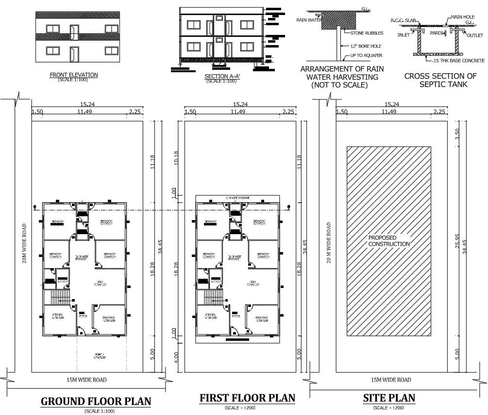
Checks to perform:
Compare overall dimensions with the relevant internal dimensions.
Verify wall thicknesses and openings against the current layout.
Check that dimension lines clearly refer to the intended building elements.
Remove obsolete dimensions left over from previous revisions.
Confirm that written measurements agree with the geometry shown in the drawing.
Where a discrepancy exists, identify the source of the error before changing the displayed measurement. The dimension should represent the intended and verified design, not simply be adjusted to match another incorrect value.
4. Inconsistent Levels and Vertical Heights
Vertical information is essential for understanding the relationship between floors, the plinth, the roof, and the surrounding ground. A mismatch between levels can make the proposed building difficult to interpret.
Typical warning signs:
Floor levels are labelled differently on related sheets.
Plinth height is inconsistent between the plan notes and section.
Staircase landings do not align with the intended floor levels.
Ground and finished floor levels are not clearly distinguished where required.
Building height information does not agree with the elevations or sections.
How to improve accuracy:
Establish a consistent level reference for the project.
Verify floor-to-floor heights and staircase landings.
Compare the vertical dimensions in sections with the elevation.
Use clear level labels and units.
Confirm building height calculations against the applicable local rules.
Level information should be coordinated with the actual design and relevant site conditions rather than copied from an unrelated drawing template.
5. Ambiguous Room Names and Drawing Symbols
A submission drawing should communicate its intended meaning without requiring the reviewer to guess what a symbol or label represents. Poor annotation can reduce the usefulness of an otherwise accurate drawing.
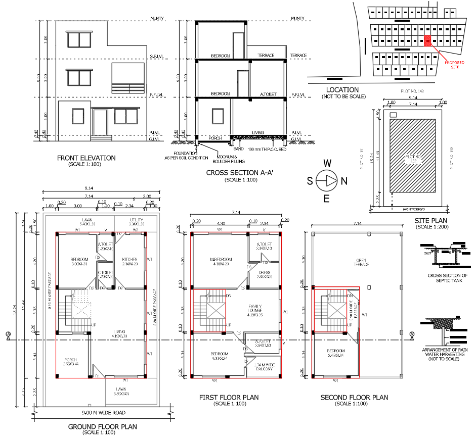
Common problems include:
Room names that are missing or difficult to read.
Symbols that are used inconsistently across sheets.
Text placed over walls, dimensions, or other important information.
Abbreviations that are not explained when clarification is needed.
Notes that refer to building elements that are no longer present.
Ways to resolve these problems:
Maintain a readable text hierarchy for titles, dimensions, and notes.
Position annotations so they do not obscure essential geometry.
Explain project-specific symbols when necessary.
Remove outdated notes after design changes.
The objective is to make each sheet understandable at its intended printed scale, not merely readable when zoomed in on a computer screen.
6. Drawing Scale and Printed Output Problems
A drawing can look clear in a CAD workspace but become difficult to read after printing or exporting to PDF. Text, dimensions, line weights, and symbols may not reproduce as expected.
Organizing drawing elements correctly can improve readability and make revisions easier. Learn more about AutoCAD layer standards for professional submission drawings to understand how a consistent layer structure supports better drawing management.
Why this happens:
Viewport scales are set incorrectly.
Text heights are unsuitable for the final sheet size.
Line weights are too similar to distinguish important elements.
Plot settings produce faint or overly heavy lines.
The drawing is exported with incorrect page dimensions.
Quality checks:
Verify the intended scale of every viewport.
Check paper size, orientation, and printable area.
Review text and dimensions in the exported PDF.
Confirm that essential lines remain distinguishable in monochrome printing.
Inspect the final output at realistic print size.
For example, a wall outline and a dimension line should not become visually indistinguishable in the final output. The appropriate line-weight hierarchy depends on the drawing standard and submission requirements being followed.
To improve drawing readability, check the lineweight settings before printing or exporting architectural drawings to PDF. Autodesk’s official guide to AutoCAD lineweights explains how lineweights affect the appearance of drawing elements in the final output.
7. Poor Revision and File Management
Design changes are a normal part of architectural work. The problem occurs when the team cannot identify which drawing version contains the latest approved information.
This can lead to outdated sheets being combined into one submission packag
Preventive measures:
Use a consistent file-naming convention.
Maintain revision numbers or dates where appropriate.
Record significant design changes.
Update all dependent sheets after a revision.
Remove superseded files from the final issue folder.
Check that the title block and revision information match the issued drawing.
A simple revision register can help record the drawing number, revision, date, change description, and responsible person. This creates a clearer record of what was changed and which documents require updating.
8. Missing Coordination Between Architectural and Service Information
Architectural layouts may need to coordinate with drainage, plumbing, electrical, or other building services. When these elements are developed without reference to the same layout, conflicts can appear.
Examples of coordination issues:
A service route conflicts with a wall or other building element.
A drainage point is shown in a location that differs between drawings.
A service opening is missing from the relevant coordinated information.
Different sheets show inconsistent locations for service-related features.
How to reduce these problems:
Coordinate service locations with the current architectural layout.
Compare the applicable drawings before issuing the package.
Refer technical conflicts to the responsible professional.
Revise affected sheets together rather than correcting only the first sheet where the problem is noticed.
The required level of service information varies by building type and authority. Include the documents and details required for the particular project instead of assuming that every submission follows the same format.
9. Incomplete Project References and Sheet Identification
A technically detailed drawing can still create confusion if the reviewer cannot identify the project, drawing purpose, or relationship between sheets.
Details to verify:
Project and drawing titles are consistent.
Drawing numbers are unique and logically organized.
Scale and units are identified where required.
Revision information reflects the current issue.
The responsible designer or professional details are included where applicable.
References to related drawings point to the correct sheets.
Check the title block against the actual contents of each sheet. A sheet labelled as a ground-floor plan should not contain an outdated layout or an unrelated drawing.
10. Failure to Review the Final Submission Package as a Whole
A drawing-by-drawing review is useful, but it may not reveal every coordination problem. The final package should also be reviewed as a complete set.
Use this final review process:
Confirm the drawing list: Check that all sheets and documents required by the relevant authority are included.
Check design consistency: Compare key dimensions, openings, levels, and building elements across related sheets.
Verify project information: Review drawing titles, numbers, dates, and revision references.
Inspect the exported files: Open the actual PDFs intended for submission and check readability.
Resolve outstanding comments: Make sure known discrepancies have been addressed or formally clarified.
Confirm applicable regulations: Verify the project against the current local building rules and submission requirements.
Obtain the required review: Have the responsible architect, engineer, or other qualified professional complete the checks appropriate to the project.
Keep a record of unresolved items and their status. A documented review process is more reliable than relying on memory or assuming that a drawing is correct because it looks finished.
Before submitting a building plan, verify the applicable local building regulations and relevant provisions of the National Building Code of India to ensure that the drawings meet the requirements applicable to the project.
A Practical Method for Finding Errors Before Submission
A useful approach is to review drawings in three passes.
Pass 1: Individual sheet review
Check the readability, dimensions, annotations, scale, drawing title, and general completeness of each sheet.
Pass 2: Cross-drawing review
Compare the floor plans, elevations, sections, site information, and relevant service drawings. Focus on elements that appear on more than one sheet.
Pass 3: Submission package review
Check the complete file set, revision status, required supporting documents, print quality, and project-specific approval requirements.
This method separates different types of checking and makes it easier to record corrections systematically.
Conclusion
Reliable submission drawings depend on more than correct drafting. They require consistent design information, verified dimensions, clear annotations, coordinated revisions, and a final review of the complete drawing package.
By identifying discrepancies early and following a structured quality-control process, design professionals can reduce avoidable rework and communicate the proposed building more effectively. However, no drawing review can guarantee approval; the final submission must satisfy the requirements of the relevant local authority and be reviewed by the appropriate qualified professionals.
Frequently Asked Questions
What is the most important check before issuing submission drawings?
One of the most valuable checks is consistency between related drawings. Confirm that important dimensions, openings, levels, and other shared design information agree across the relevant sheets.
Why can a drawing look correct but still contain errors?
A drawing may appear visually complete while containing outdated dimensions, conflicting references, or information that does not match another sheet. Reviewing the complete drawing set helps reveal these issues.
How can I reduce drawing revisions?
Use a controlled revision process, maintain a clear source of current design information, update dependent sheets together, and inspect the final exported files before issuing them.
Should every building submission contain the same drawings?
No. Required drawings and supporting documents depend on the building type, project scope, and applicable local authority requirements. Confirm the exact submission requirements before preparing the final package.
Who should review submission drawings before they are issued?
The review should be carried out by the responsible architect, engineer, drafter, or other qualified project professional according to their role and applicable regulations. Specialist information should be checked by the relevant professional.
Does a technically correct drawing guarantee building approval?
No. Approval also depends on applicable regulations, site conditions, required documentation, and the authority’s review. Accurate drawings help communicate the design but cannot guarantee a particular approval outcome.