
How to Create Submission Drawings in AutoCAD – A Complete Guide
Introduction
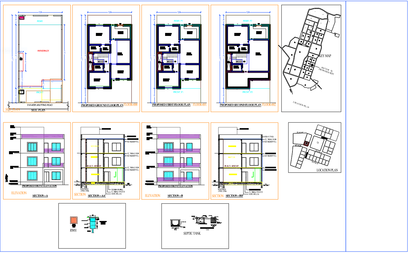
Submission Drawings in AutoCAD constitute an essential part of the building plan approval process. Before commencing construction, architects and engineers are required to submit a set of drawings to the local municipal authority for approval. These drawings include the building plan, elevations, sections, site plan, and other necessary details.
In this guide, we will provide a step-by-step explanation of how to create submission drawings in AutoCAD; this covers the necessary drawings, layer setup, dimensioning, and plotting for submission.
What Are Submission Drawings?
Submission Drawings in AutoCAD are technical drawings prepared to obtain approval from local authorities before commencing construction work. These drawings depict the building’s design, layout, dimensions, setbacks, and structural details.
They assist municipal authorities in verifying the following:
- Compliance with building bylaws
- Plot area and setbacks
- Floor Area Ratio (FAR)
- Building height
- Parking arrangements
- Structural safety
The authorities responsible for granting such approvals typically include municipal corporations, development authorities, and town planning departments.
Software Required for Submission Drawings
The most widely used software for preparing submission drawings includes:
- AutoCAD
- Revit (for BIM projects)
- SketchUp (for conceptual support)
However, AutoCAD remains the most frequently used tool for 2D submission drawings, as it is user-friendly, precise, and accepted by most authorities.
Types of Submission Drawings Required for Building Approval
A complete set of suSubmission Drawings in AutoCAD typically includes the following items:
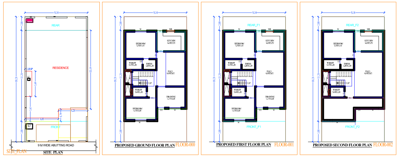
1. Site Plan
The site plan illustrates the location of the building within the plot.
Key elements include:
- Plot boundaries
- Access to the road
- North direction
- Setbacks
- Building footprint
- Parking area
- Landscaped area
2. Floor Plan
This floor plan illustrates the layout of every floor of the building.
Included details:
- Room layout
- Wall thickness
- Doors and windows
- Staircases
- Dimensions
- Room names
- Area calculations
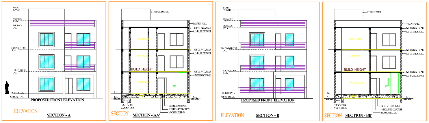
3. Building Elevation
Elevation drawings depict the exterior appearance of the building.
Key details:
- Building height
- Floor levels
- Window placement
- Exterior design
- Roof details
4. Section Drawing
This section presents a vertical cross-section of the building’s interior.
These drawings help officials understand:
- Floor heights
- Foundation levels
- Staircase details
- Structural arrangement
5. Parking Layout
This parking drawing illustrates the arrangement for vehicle parking.
It includes:
- Car parking dimensions
- Access routes
- Circulation space
6. Area Details
This document includes:
- Plot area
- Built-up area
- Ground coverage
- FAR calculation
- Total construction area
A Step-by-Step Guide to Creating Submission Drawings in AutoCAD
Step 1: Set Drawing Units
First, configure the drawing units.
Steps:
- Type UN in the command line
- Select Decimal units
- Set the Precision
- Set the Insertion scale to meters or millimeters
- This ensures accurate measurements.
Step 2: Create Layers
Layers help organize the drawing properly in AutoCAD. By placing different elements on separate layers, the drawing becomes easier to manage and edit.
Typical Layer Setup:
Wall Layer – Used for drawing building walls
Door Layer – Used for door blocks
Window Layer – Used for window blocks
Text Layer – Used for annotations and room names
Dimension Layer – Used for all dimensions
Furniture Layer – Used for furniture layout blocks
Plot Boundary Layer – Used for drawing the plot outline
Using different colors and line weights for each layer helps make the drawing clear, organized, and easy to read in submission drawings.
Step 3: Create the Plot Boundary
In this step, we begin by establishing the dimensions of the plot.
Examples:
- 30×40 plot
- 40×60 plot
- 50×80 plot
- Commands used:
- LINE
- OFFSET
- TRIM
Add setbacks (open spaces) in accordance with local regulations.
Step 4: Create the Building Layout
Now, construct the building’s walls.
Steps:
- Create the exterior walls using the LINE command
- Set the wall thickness using the OFFSET command
- Use the TRIM command to clean up the corners
- Add interior partition walls
- Standard wall thickness:
- 230 mm for exterior walls
- 115 mm for interior walls
Step 5: Insert Doors and Windows
Utilize AutoCAD blocks for the doors and windows.
Commands used:
- INSERT
- ROTATE
- MIRROR
Standard dimensions:
Door sizes:
- Main door: 1000–1200 mm
- Bedroom door: 900 mm
- Toilet door: 750 mm
- Window sizes:
- 1200 × 1200 mm
- 1500 × 1200 mm
Step 6: Add the Staircase Design
The staircase design must adhere to standard regulations.
General staircase specifications:
- Riser (Height): 150–175 mm
- Tread (Width): 250–300 mm
- Staircase width: 900–1200 mm
Use the ARRAY or COPY command to create the staircase steps.
Step 7: Add Room Names and Text
Add labels to identify the various spaces. Examples:
- Living Room
- Bedroom
- Kitchen
- Toilet
- Balcony
Command Used:
- TEXT or MTEXT
Step 8: Add Dimensions
Providing dimensions is mandatory for the submission to be approved.
Essential dimensions include:
- Room sizes
- Wall thickness
- Plot dimensions
- Setbacks
- Commands Used:
- DIMLINEAR
- DIMALIGNED
- DIMSTYLE
Step 9: Create the Elevation Drawing
Create the front elevation based on the floor plan.
Steps:
- Project the wall lines vertically (upwards)
- Add window locations
- Create the parapet wall
- Add levels
Include:
- Ground Level
- Plinth Level
- Floor Level
Step 10: Create the Building Section
Create a vertical section of the building. Include:
- Foundation
- Plinth Beam
- Floor Slab
- Stairs
- Roof Slab
Step 11: Prepare the Layout Sheet for Printing
Create a layout sheet for submission.
Steps:
- Go to the Layout tab
- Insert a title block
- Create a viewport
- Set the scale (1:100 or 1:50)
- Lock the viewport
Common Scales:
- Floor Plan – 1:100
- Site Plan – 1:200
- Section – 1:100
Step 12: Plot the Drawing
Finally, print the drawing.
Steps:
- Press Ctrl + P
- Select the plotter
- Select the paper size (A1 / A2)
- Set the scale
- Check line weights
- Plot to PDF
Essential Tips for Submission Drawings
✔ Adhere to local building regulations
✔ Maintain the correct scale for the drawings
✔ Use accurate dimensioning
✔ Indicate the North direction on the site plan
✔ Include a title block and drawing number
✔ Ensure the drawings are clear and legible
Common Mistakes to Avoid
❌ Incorrect plot dimensions
❌ Missing setback dimensions
❌ Omission of the North direction
❌ Incorrect scale
❌ Incomplete set of drawings
These errors can lead to the rejection of the building plan.
Benefits of Using AutoCAD for Submission Drawings
These benefits include:
- High accuracy
- Easy editing
- Professional presentation
- Rapid drafting
- Compatibility with municipal submission formats
AutoCAD helps architects and engineers prepare professional approval drawings quickly and efficiently.
Conclusion
Submission Drawings in AutoCAD Creating submission drawings using AutoCAD is an essential skill for architects, civil engineers, and AutoCAD drafters. By adhering to a systematic workflow—spanning from site planning to final plotting—one can produce professional-quality drawings that meet municipal approval standards.
Through the proper use of layers, dimensioning, and layout setups, AutoCAD renders the process of creating submission drawings precise, efficient, and organized.
A submission drawing is a set of technical drawings submitted to municipal authorities for building approval before construction begins.
Common scales are 1:100 for floor plans and 1:200 for site plans.
AutoCAD is the most widely used software for preparing submission drawings.
Site plan, floor plan, elevation, section, parking layout, and area statement are typically required.