
How to Prepare Elevation Drawings for Building Approval (A Complete Guide)
Introduction
Elevation drawings are one of the most crucial components of the building approval process. They depict the exterior appearance of a building and assist authorities in verifying whether the design complies with local building codes and regulations.
In this guide, we will walk you through a detailed, step-by-step process on how to prepare professional elevation drawings for submission.
📌 What is an Elevation Drawing?
An elevation drawing is a 2D representation of a building’s exterior, viewed from one side. It illustrates the details of the building, including:
- The building’s height
- Exterior design and finishes
- Doors, windows, and balconies
- Architectural style
📊 Types of Elevation Drawings
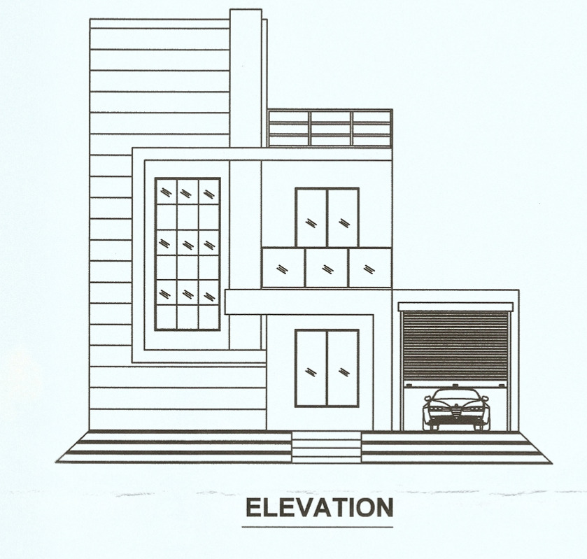
- Front Elevation – The main view facing the street
- Rear Elevation – The view facing the rear
- Side Elevation (Left and Right) – Views of the sides of the building
📐 Importance of Elevation for Approval
Authorities check elevation drawings to ensure:
- Building height complies with rules
- Proper setbacks are maintained
- Aesthetic control (in some areas)
- No illegal projections
Step-by-Step Process to Prepare Elevation Drawings
Step 1: Study Approved Floor Plan
Before starting:
- Use the approved building plan
- Verify dimensions, levels, and setbacks
- Ensure alignment of walls, doors, and windows
Step 2: Set Drawing Scale
Use standard scales such as:
- 1:100 (most common)
- 1:50 (detailed drawings)
- Maintain consistency with submission drawings.
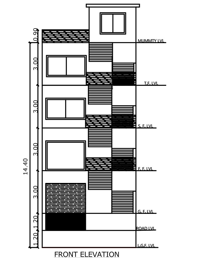
Step 3: Draw Ground Line & Plinth Level
- Mark Natural Ground Level (NGL)
- Show Plinth Level (typically 450–600 mm above ground)
- Indicate road level if required
Step 4: Project Building Features
From the floor plan:
- Project walls vertically
- Add doors, windows, ventilators
- Show balcony projections and chajjas
Step 5: Define Floor Heights
Clearly mention:
- Floor-to-floor height (e.g., 3.0 m)
- Parapet height (e.g., 1.0 m)
- Total building height
Step 6: Add Architectural Elements
Enhance elevation with:
- Cladding / textures
- Sunshades (Chajja)
- Railings
- Cornices
- Glass panels
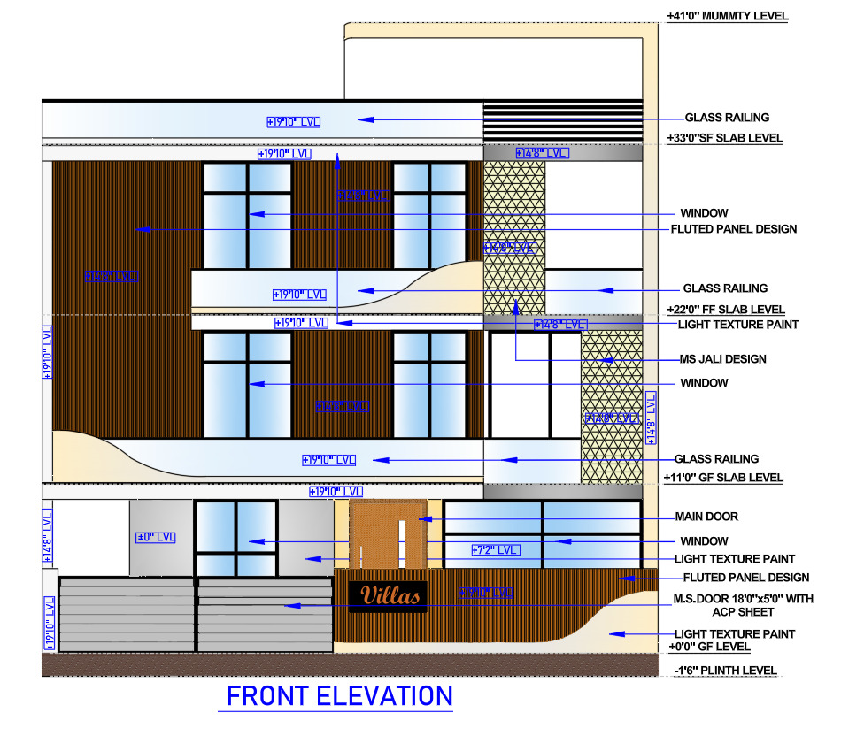
Step 7: Show Levels & Dimensions
Important levels to mark:
- Ground Level
- Plinth Level
- Lintel Level
- Roof Level
- Parapet Level
Add vertical dimensions for approval clarity.
Step 8: Material & Finish Details
Mention materials such as:
- Paint finish
- Stone cladding
- Brick texture
- Glass curtain wall
Step 9: Follow Local Bye-Laws
Check compliance with:
- Maximum height limit
- Projection rules
- Balcony restrictions
- Architectural control guidelines
Step 10: Add Title Block & Notes
Include:
- Project name
- Owner name
- Drawing title (Elevation)
- Scale
- Date
- Architect/Engineer signature
Elevation Drawing in AutoCAD (Quick Workflow)
- Use XLINE / Projection lines
- Draw vertical walls using LINE / POLYLINE
- Add openings (doors/windows blocks)
- Apply HATCH for materials
- Add dimensions using DIMLINEAR
Use layers properly:
Layer Setup Example:
- Wall
- Window
- Door
- Text
- Dimension
- Hatch
⚠️ Common Mistakes to Avoid
❌ Incorrect building height
❌ Missing levels (plinth, roof)
❌ No dimensions
❌ Over-designed façade (not matching plan)
❌ Ignoring local authority rules
Checklist Before Submission
✔ All elevations (front, rear, sides) included
✔ Heights and levels clearly marked
✔ Scale mentioned
✔ Materials specified
✔ Matches floor plan exactly
✔ Signed by licensed professional
Conclusion
Creating an accurate elevation drawing is essential for obtaining building approval with ease. This not only ensures compliance with regulations but also defines the visual identity of your project.
By following the step-by-step process outlined above, you can easily create professional-quality elevation drawings that are ready for approval.
Yes, elevation drawings are required to verify the external appearance and building height.
Common scales are 1:100 or 1:50 depending on detail level.
No, elevation must match the approved floor plan layout.
- Height
- Levels
- Openings
- Materials
- External design