
AutoCAD Layer Standards for Professional Submission Drawings
Introduction
In architectural and civil engineering projects, AutoCAD layer standards play a crucial role in creating clear, organized, and professional submission drawings. Whether you are preparing drawings for municipal approval or for client presentations, proper layer management ensures accuracy, legibility, and compliance with standards.
What Are AutoCAD Layers?
In AutoCAD, layers are like transparent sheets where different elements of a drawing are organized separately. Each layer can have its own specific properties:
- Color
- Line Type
- Line Weight
- Visibility Settings
This helps in efficiently managing complex drawings.
Why AutoCAD Layer Standards Are Important
Using standardized layers in submission drawings offers multiple benefits:
1. Better Drawing Organization
- Keeps elements like walls, doors, text, and dimensions separate
- Makes editing easier
2. Improved Readability
- Different colors and line weights enhance clarity
- Helps authorities quickly understand drawings
3. Faster Workflow
- Reduces confusion during drafting
- Saves time in revisions
4. Professional Presentation
- Creates uniform and clean drawings
- Essential for approvals and client trust
AutoCAD Layer Standards Naming Conventions
A consistent naming system is key for professional work. Use clear and descriptive names:
Recommended Format:
Discipline_Element_Type
Examples:
- A-WALL
- A-DOOR
- A-WINDOW
- A-TEXT
- A-DIMS
- S-COLUMN
- S-BEAM
- E-LIGHT
- P-PIPE
Typical AutoCAD Layer Standards Setup for Submission Drawings (Step-by-Step Guide)
Creating a proper layer setup in AutoCAD is essential for professional submission drawings. Follow this structured process to organize your drawings efficiently.
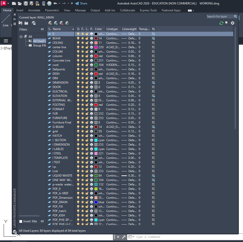
Step 1: Open Layer Properties Manager
- Type LA in the command line
- Press Enter
- The Layer Properties Manager window will open
👉 This is where you will create and manage all layers.
Step 2: Create New Layers
- Click on New Layer icon
- Start creating layers one by one
Basic Layers to Create:
- Wall
- Door
- Window
- Column
- Beam
- Text
- Dimension
- Furniture
- Hatch
- Center Line
- Hidden Line
- Plot Boundary
Step 3: Apply Naming Convention
Use clear and professional naming:
Recommended Format:
- A-WALL
- A-DOOR
- A-WINDOW
- S-COLUMN
- S-BEAM
- A-TEXT
- A-DIMS
- F-FURNITURE
- A-HATCH
👉 Prefix Meaning:
- A = Architectural
- S = Structural
- E = Electrical
- P = Plumbing
Step 4: Assign Colors to Layers
Assign different colors for clarity:
- Wall → Red
- Door → Yellow
- Window → Green
- Column → Cyan
- Beam → Blue
- Text → White
- Dimension → Magenta
- Furniture → Grey
👉 Colors help in visual clarity and plotting (CTB settings)
Step 5: Set Line Types
Assign appropriate line types:
- Continuous → Walls, Doors, Windows
- Hidden → Hidden elements
- Center → Center lines
👉 Load line types if not available:
- Click Linetype → Load → Select (Hidden, Center)
Step 6: Set Line Weights
Define line thickness for plotting:
- Walls / Columns → 0.50 mm
- Doors / Windows → 0.35 mm
- Furniture → 0.25 mm
- Text / Dimensions → 0.18 mm
👉 This creates proper line hierarchy
Step 7: Set Current Layer
Select a layer (e.g., A-WALL)
Click Set Current
👉 Always draw objects on the correct layer.
Step 8: Organize Drawing Elements
Draw using correct layers:
- Walls → A-WALL
- Doors → A-DOOR
- Windows → A-WINDOW
- Text → A-TEXT
- Dimensions → A-DIMS
👉 Avoid mixing multiple elements in one layer.
Step 9: Use Layer Control Tools
Use these options effectively:
- On/Off → Show or hide layers
- Freeze/Thaw → Improve performance
- Lock/Unlock → Prevent editing
Step 10: Save as Template (.DWT)
Go to Save As
Select Drawing Template (*.dwt)
Save as: Submission_Layer_Standard.dwt
👉 This saves time for future projects.
Step 11: Check Before Submission
Before final plotting:
✔ All elements are on correct layers
✔ Line weights are properly assigned
✔ Unused layers are removed
✔ Text and dimensions are clear
✔ Plot preview is checked
Color and Line Weight Standards
Common Practice:
- Thick Lines (0.5 mm – 0.7 mm): Walls, columns
- Medium Lines (0.3 mm – 0.4 mm): Doors, windows
- Thin Lines (0.18 mm – 0.25 mm): Text, dimensions
Color Guidelines:
- Use colors that convert properly in CTB plot styles
- Maintain consistency across all drawings
AutoCAD Layer Standards Management Best Practices
1. Use Layer Templates
- Create a standard .dwt template file
- Saves time in every project
2. Avoid Layer Overload
- Don’t create unnecessary layers
- Keep it simple and logical
3. Lock and Freeze Layers
- Lock important layers to avoid accidental edits
- Freeze unused layers for better performance
4. Use Layer States
- Save different layer visibility settings
- Helpful for plan, section, and elevation views
5. Maintain Discipline Separation
Separate layers for Architecture, Structure, Electrical, Plumbing
Common Mistakes to Avoid
❌ Using random layer names (Layer1, Layer2)
❌ Same color for all elements
❌ Ignoring line weights
❌ Mixing multiple elements in one layer
❌ Not using templates
AutoCAD Layer Standards for Different Drawings
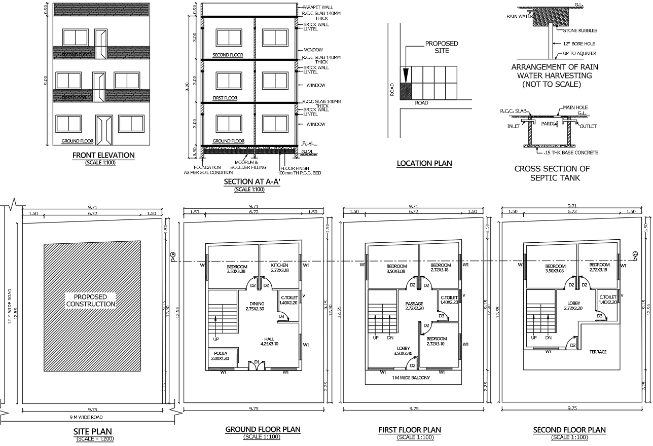
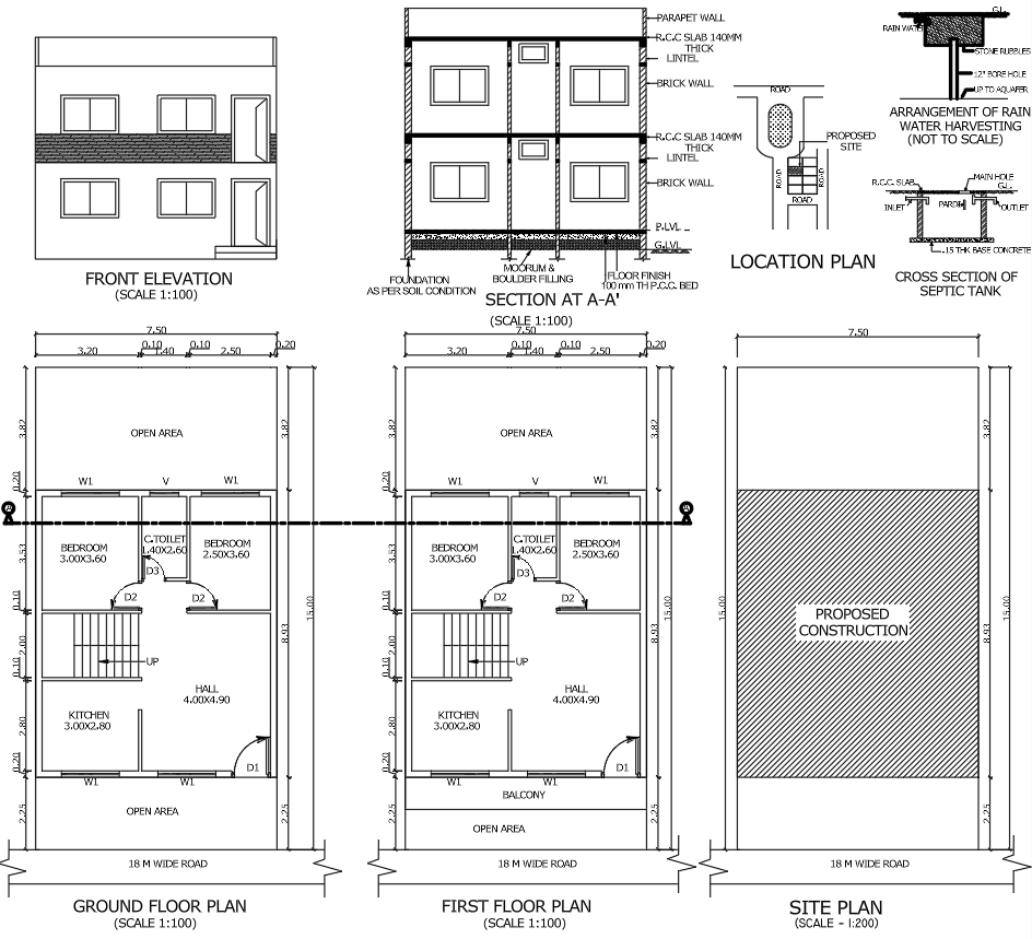
1. Floor Plans
Walls, doors, windows, furniture, dimensions
2. Elevations
External walls, levels, textures, annotations
3. Sections
Cut elements (thick lines), background elements (thin lines), hatching
4. Site Plans
Plot boundary, roads, landscaping, north direction
Tips for Submission Drawings Approval
- Follow local authority guidelines
- Maintain proper line hierarchy
- Use readable text sizes
- Keep layers clean and organized
- Ensure proper plotting settings
Conclusion
AutoCAD layer standards serve as the backbone of professional submission drawings. A well-organized layer system not only enhances the quality of the drawings but also accelerates the approval process. By adhering to proper naming conventions, line weights, and management protocols, architects and engineers can consistently deliver accurate and high-quality drawings.