
Submission Drawing Checklist for Architects and Engineers (Complete Guide)
Introduction
Submission drawings constitute a crucial part of the building approval process. Whether you are an architect, a civil engineer, or a designer, having a comprehensive checklist ensures that your drawings are accurate, compliant with regulations, and receive prompt approval from the authorities.
In this guide, we provide a complete checklist for submission drawings, designed to help you avoid drawing rejections and streamline the approval process.
What are Submission Drawings?
Submission drawings are a set of technical drawings submitted to local authorities for approval before construction work begins. It is mandatory for these drawings to comply with building by-laws, zoning regulations, and safety standards.
Why Is a Checklist Important?
A proper checklist helps:
- Avoid missing critical details
- Ensure compliance with regulations
- Reduce approval delays
- Improve drawing quality and clarity
Complete Submission Drawing Checklist
1. Basic Project Information
Ensure the following details are clearly mentioned:
- Project title and type (Residential/Commercial)
- Owner’s name and details
- Architect/Engineer name, license number
- Site address and location
- Drawing number and revision details
- Scale of drawing
2. Site Plan Checklist
The site plan is one of the most important drawings.
Include:
- Plot boundaries with dimensions
- North direction
- Road width and access points
- Setbacks (front, rear, side)
- Existing structures (if any)
- Parking layout
- Drainage and sewer lines
- Water supply connection
- Landscape details
3. Building Plan (Floor Plan) Checklist
Each floor plan must show:
- Wall thickness and layout
- Room names and sizes
- Door and window positions
- Staircase details
- Lift (if applicable)
- Ventilation and lighting provisions
- Furniture layout (optional but useful)
- Dimensions (clear and readable)
4. Elevation Drawing Checklist
Elevation drawings should include:
- Front, rear, and side elevations
- Building height
- Floor levels
- Architectural features
- External finishes
- Ground level and plinth level
5. Section Drawing Checklist
Sections provide internal details of the building.
Must include:
- Foundation details
- Plinth level
- Floor heights
- Slab thickness
- Staircase section
- Roof structure
- Natural ground level (NGL) and finished floor level (FFL)
6. Structural Drawing Checklist
Required for safety and stability:
- Foundation layout
- Column layout
- Beam and slab details
- Reinforcement details
- Structural notes and specifications
7. Services Drawings Checklist
Include basic service layouts:
- Electrical Plan
- Light points
- Switches
- Distribution board
- Plumbing Plan
- Water supply lines
- Drainage layout
- Septic tank/soak pit
- Fire Safety Plan (if required)
- Fire exits
- Extinguishers
- Staircase width compliance
8. Area Statement & Calculations
Clearly mention:
- Plot area
- Built-up area
- Floor-wise area
- FSI/FAR calculation
- Ground coverage
- Parking calculations
9. Required Documents Checklist
Attach the following documents:
- Ownership proof
- Site photographs
- Previous approvals (if any)
- Structural stability certificate
- Soil test report (if required)
- NOC from relevant authorities
10. Drawing Presentation Checklist
Ensure professional quality:
- Proper line weights
- Standard symbols
- Legible text size
- Clean layout
- Consistent scales
- Title block with all details
11. Compliance Checklist
Verify:
- Local building bye-laws followed
- Zoning regulations met
- Height restrictions
- Setback rules
- Parking norms
- Fire safety rules
Common Mistakes to Avoid
- Missing dimensions
- Incorrect setbacks
- No north direction
- Poor layer management in CAD
- Incomplete structural details
- Mismatch between drawings
Pro Tips for Faster Approval
- Always cross-check with local authority guidelines
- Use standard CAD templates
- Maintain proper layer naming
- Double-check calculations
- Keep drawings simple and clear
Conclusion
A well-crafted submission drawing checklist ensures accuracy, regulatory compliance, and expedited approval. By adhering to this checklist, architects and engineers can minimize errors, avoid rework, and deliver professional-quality drawings.
Submission drawings are a set of technical drawings submitted to local authorities for building approval. They include plans, elevations, sections, and service layouts required before construction starts.
Submission drawings are prepared by:
- Architects
- Civil Engineers
- Licensed Building
- Designers
They must be signed and approved by a registered professional.
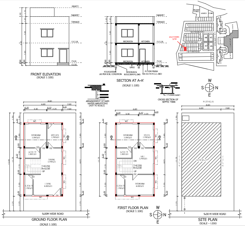
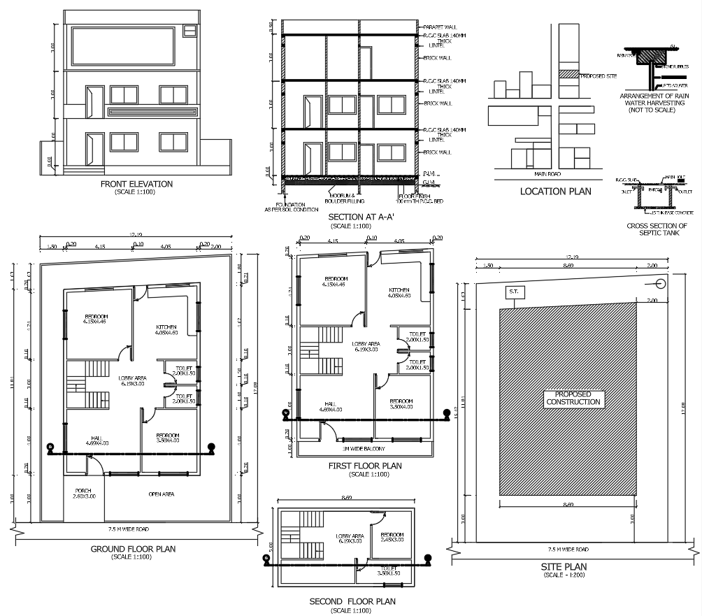
Typically, submission drawings include:
- Site plan
- Floor plans
- Elevations
- Sections
- Structural drawings
- Electrical and plumbing layouts
Submission drawings → Used for approval from authorities
Working drawings → Used for actual construction on site
Working drawings contain more detailed information than submission drawings.
A site plan shows:
- Plot boundaries
- Building position
- Setbacks
- Road access
- Utilities
It helps authorities understand how the building fits on the plot.